¶ When to use?
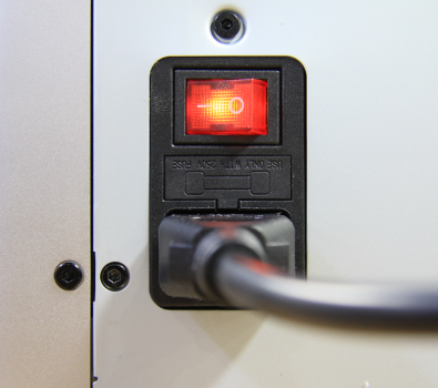
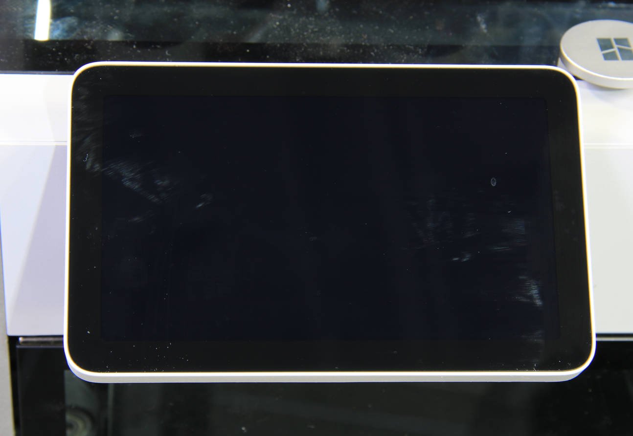
After connecting the power cord and turning on the power, although the power indicator lights up, the printer's screen does not receive power. At the same time, one or more circuit board indicator lights are malfunctioning.
Some of the videos in this guide may not load properly when viewed on a mobile browser. It is recommended to use a desktop/PC browser to access this content.
 |
 |
¶ Normal State: the TH board indicator light is constantly red
https://public-cdn.bblmw.com/wiki/video/X1-TH.mp4
¶ Normal State: the MC board flashes red once every 5 seconds
https://public-cdn.bblmw.com/wiki/video/X1-MC.mp4
¶ Normal State: the AP board has 2 indicator lights, one is constantly red, and the other flashes red once per second
https://public-cdn.bblmw.com/wiki/video/X1-AP.mp4
¶ Distinguishing between a general printer power failure and a black screen issue limited to just the screen and AP module
If the screen is not lit, but the MC and TH indicators are normal, then the fault should be limited to just the screen, AP module, or MC-AP cable pack, and not a general circuit issue with the entire machine. In this case, you can jump to the wiki page to guide the troubleshooting process.
Troubleshooting black & flickering LCD screen and AP board
¶ Tools and materials needed
- H1.5 allen key
- H2.0 allen key
- Tweezer
¶ Safety Warning
IMPORTANT!
It's crucial to power off the printer before conducting any maintenance work, including work on the printer's electronics and tool head wires. Performing tasks with the printer on can result in a short circuit, leading to electronic damage and safety hazards.
During maintenance or troubleshooting, you may need to disassemble parts. This exposes wires and electrical components that could short circuit if they contact each other, other metal, or electronic components while the printer is still on. This can result in damage to the printer's electronics and additional issues.
Therefore, it's crucial to turn off the printer and disconnect it from the power source before conducting any maintenance. This prevents short circuits or damage to the printer's electronics, ensuring safe and effective maintenance. For any concerns or questions about following this guide, open a new ticket in our Support Page and we will do our best to respond promptly and provide the assistance you need.
¶ Possible causes of power failure
¶ 1. Faulty MicroSD card
Faulty MicroSD card causes AP board failure, indicator light off, and black screen.
¶ 2. Abnormal output of the 24V power supply unit:
The input voltage of these control boards is 24V, provided by the power supply unit. If the 24V power supply unit has abnormal output, it will cause abnormal input voltage to the control board, resulting in the indicator lights being unable to light up.
Power supply unit installation tutorial
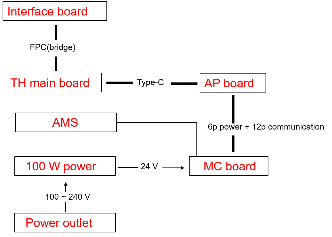
¶ 3. The 24V power supply unit is functioning normally, but due to one of the circuit boards, such as the TH board, MC board, AP board, or a component on the circuit board like a fan, heater, or motor, experiencing a 24V short circuit, it has led to a 24V short circuit in the entire printer's circuit.
The 24V supply in the machine is connected in series. If there is a short circuit in one of the main or branch circuits, it can potentially cause a short circuit in the entire 24V system of the machine.
¶ Troubleshooting guide
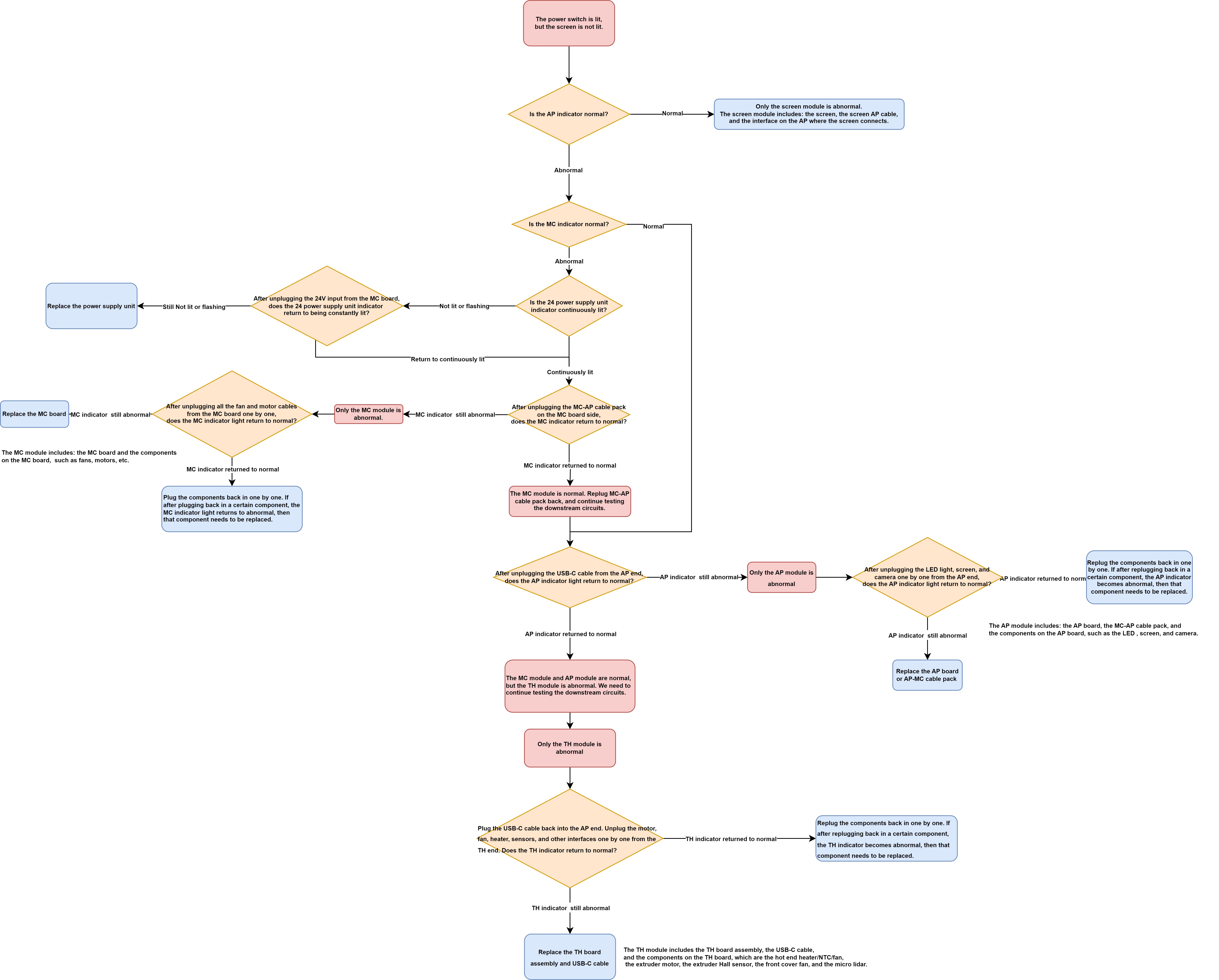
The principle behind this is that if, after disconnecting a specific connector, the remaining circuit's indicator lights return to normal, it indicates that the module connected to that connector is the one causing the abnormality. In this case, further troubleshooting or replacement of that specific module would be required.
Please note that you must turn off the printer before each connection or disconnection. After plugging or unplugging the components, you can then turn the printer on and observe the circuit status.
¶ 1. Troubleshoot the MicroSD card
Precautions: Before doing the following, be sure to turn off the printer's power
Before troubleshooting the MicroSD card, make sure that both the board and the power supply are properly powered.
- Switch off the printer and carefully remove the MicroSD card from the printer.
- Restart the printer and observe if the display lights up properly. If the display lights up normally after the MicroSD card is removed, reinsert the MicroSD card into the printer with the power off and power it on again to verify that the previous black screen problem was not caused by a faulty MicroSD card.

¶ 2. Troubleshoot the abnormal output of the 24V power supply unit
¶ Step 1 - Turn off the power switch and disconnect the power. Remove the rear panel.
Remove the metal rear panel by referring to the content of The rear panel.
¶ Step 2 - Remove the excess chute (optional).
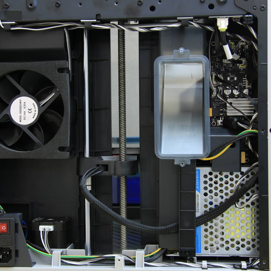
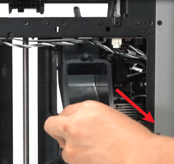
Following this guide to remove the excess chute is highly recommended to create more space for the operation.
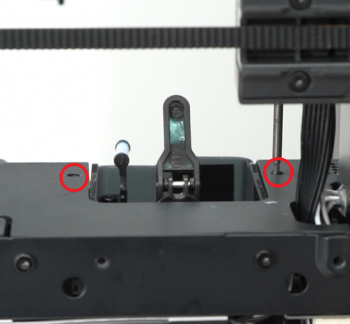
Undo the screws located at each side of the excess chute. Once done, take out the excess chute. Some printers have three screws to secure the excess chute, while some only have two; please refer to your unique situation.
Note: For some versions, the heatbed cables are fixed to the bottom of the excess chute with a buckle; do not use too much force when taking off the excess chute.
Two screws case:
 |
 |
Three screws case:
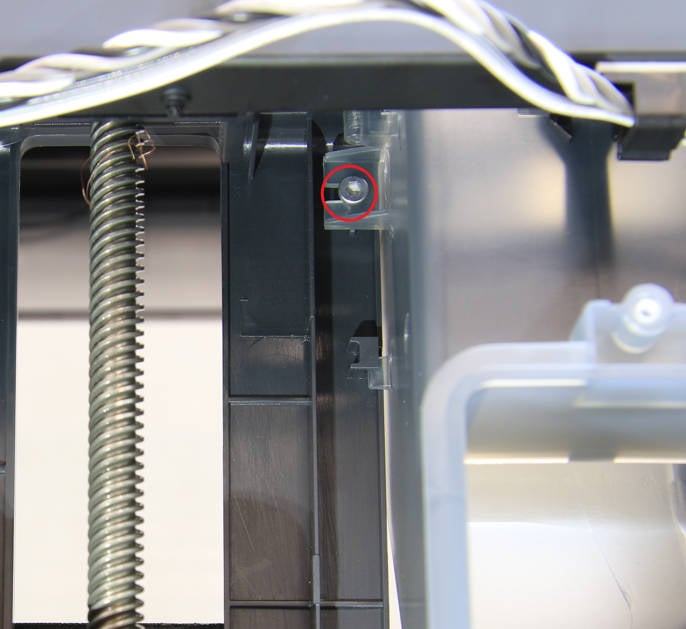 |
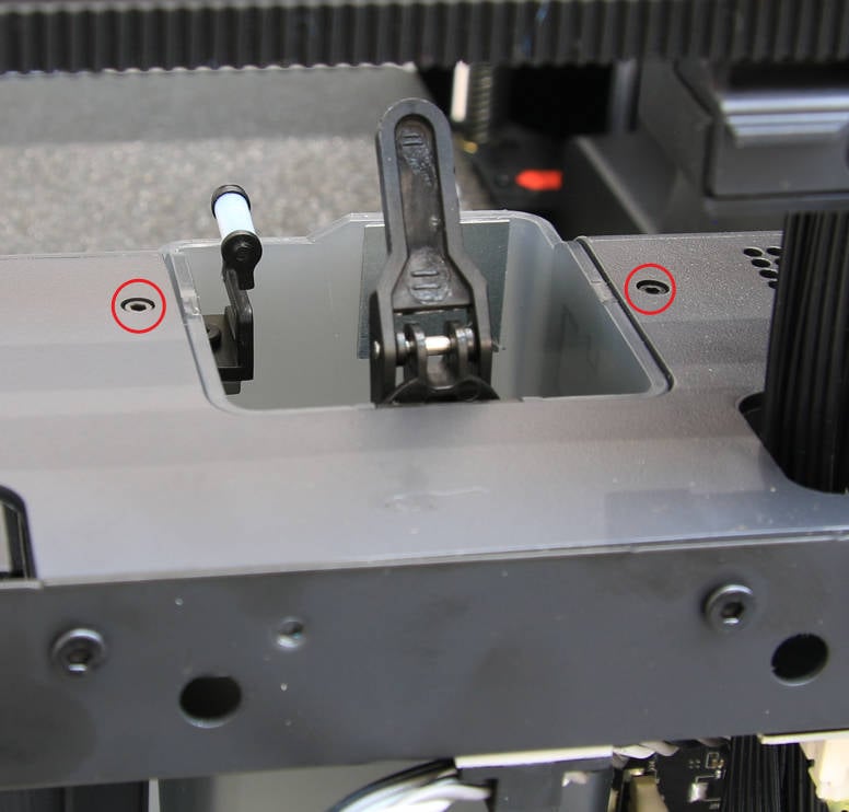 |
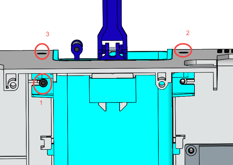 |
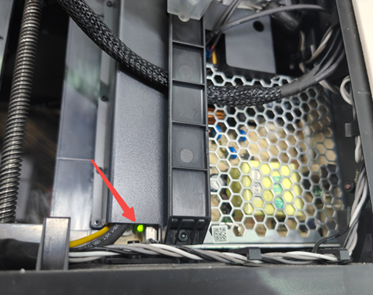
¶ Step 3: Connect the power, turn on the power switch, and observe whether the green indicator light on the 24V power supply unit is continuously lit (not lit or flashing indicates an abnormality).
Power supply unit installation tutorial

If the green indicator light is continuously lit, which means the power supply unit works normally, you can skip step 4 and start checking from step 5 of the second part.
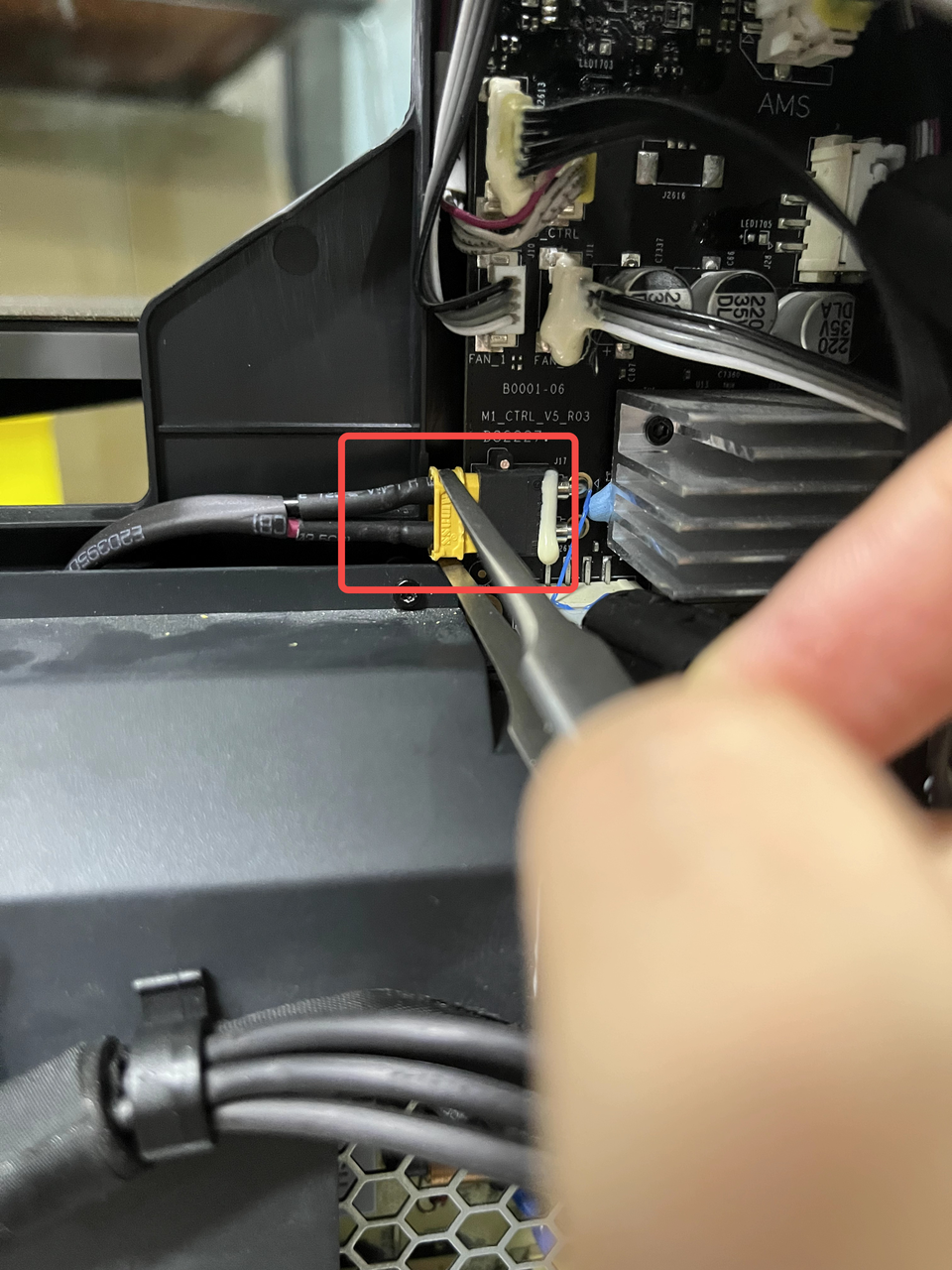
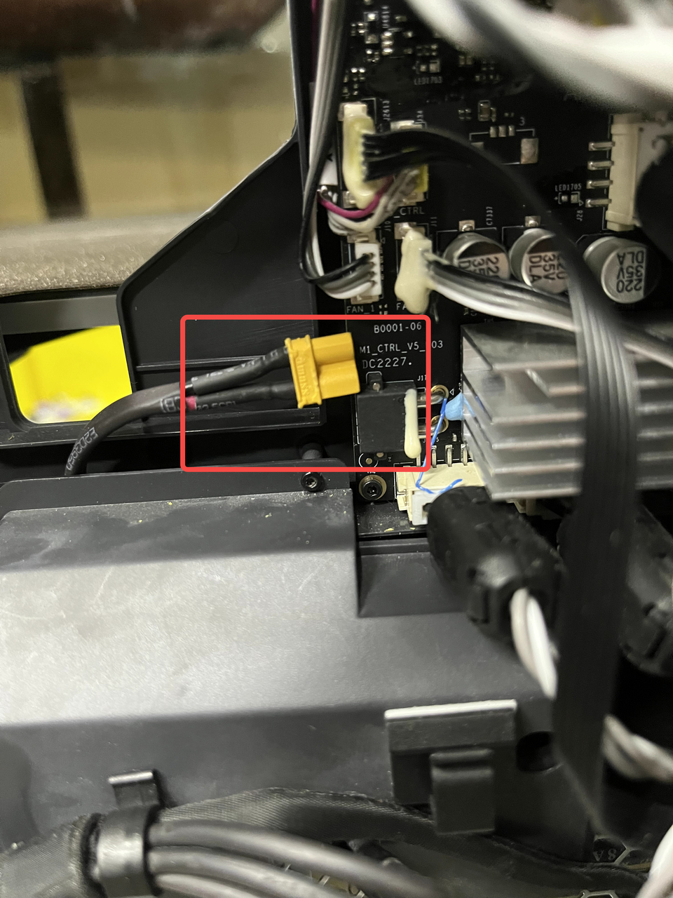
¶ Step 4 - If the green indicator light is not lit or is flashing, please turn off the printer again. Then carefully use tweezers to unplug the 24V input connector on the MC board. Restart the printer and check the status of the indicator light on the 24V power supply unit again.
Suppose the green indicator light remains unlit or is flashing even after unplugging the 24V input connector from the MC board. In that case, it suggests that the power supply unit itself is faulty and needs to be replaced. This is because by disconnecting the 24V input to the main board, you have isolated the main board and downstream circuits from the power supply. Therefore, the fault is most likely originating from the power supply itself.
On the other hand, after unplugging the connector and turning on the power switch, the indicator light on the power supply unit is continuously lit, indicating that the power supply unit is not faulty. Please proceed with the following steps for further troubleshooting.
 |
 |
¶ 3. Troubleshoot the abnormal circuit on the control board and identify the problematic component through a process of trial and error by methodically connecting and disconnecting different parts.
If the power module is confirmed to be working normally, the problem must be with one of the circuit boards (most likely the TH, MC, or AP board), or a component on these circuit boards (less likely the fans, heaters, or motors) that has a 24V short circuit, causing the entire system to short circuit. Therefore, we need to continue investigating.
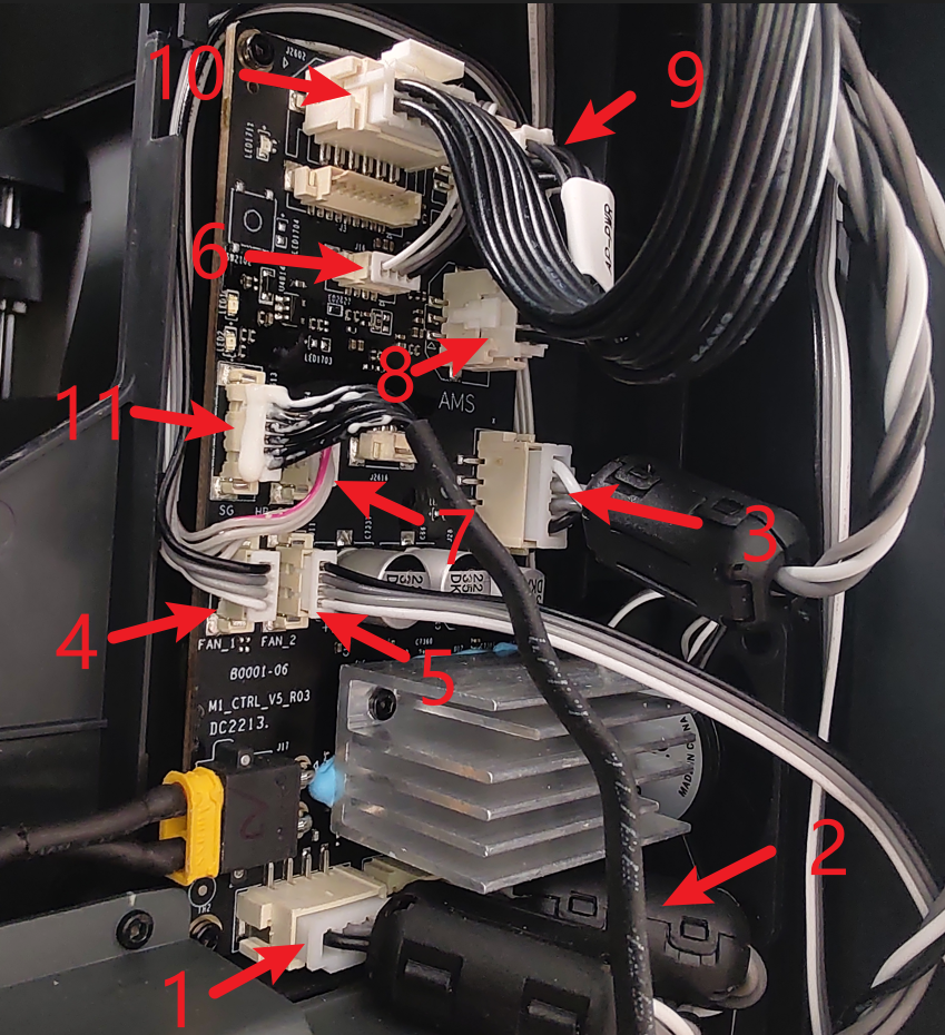
¶ Step 5: After powering off the printer, reconnect the 24V power connector to the MC board as mentioned in step 4. Then, disconnect the AP-MC cable (communication and power, #9 and #10) from the MC board, as shown in the image. Power on the printer again and check the status of the MC indicator lights.
MC board installation tutorial
| NO. | Connect object | NO. | Connect object | NO. | Connect object |
|---|---|---|---|---|---|
| 1 | Motor Z | 5 | Auxiliary part cooling fan | 9 | AP main board (Power cable) |
| 2 | The right motor (view from the rear) | 6 | MC board fan | 10 | AP main board (Communication cable ) |
| 3 | The left motor (view from the rear) | 7 | MC board to AC board connecting cable | 11 | Heat bed (Communication cable) |
| 4 | The chamber temperature regulator fan | 8 | AMS interface board |
Disconnecting the MC-AP cable pack can isolate the impact of the AP and TH modules on the MC board. This can help us determine if the MC module itself is working properly.
If the indicator light on the MC board is still abnormal after disconnecting the MC-AP cable pack on the MC board side, it means the MC module is malfunctioning.
Tips: Assuming we have narrowed down the problem to the MC module, the root cause may be the MC board itself or the components on the MC board, such as the motor or fan. But statistically, the problem is more likely to be with the MC board itself. To simplify the troubleshooting steps, I will include the isolation method for the MC board and its components at the end of this article (step 8), rather than continuing to expand on it in this step.
If the indicator on the MC board returns to normal after disconnecting the MC-AP cable pack on the MC board side, it means the MC module is working properly, and the problem may be in the downstream circuit, such as the AP module and TH module. Then you need to proceed from step 6.
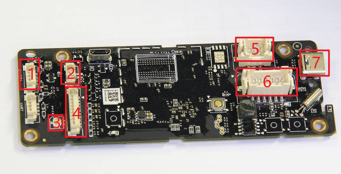
¶ Step 6: After turning off the printer power, reconnect the MC-AP cable on the MC board side, then unplug the USB-C port on the AP board to determine if the AP module is abnormal.
| NO. | Connect object | NO. | Connect object | NO. | Connect object |
| 1 | The chamber camera | 4 | Button PCBA | 7 | USB-C cable to Toolhead |
| 2 | The chamber LED | 5 | MC board (Power) | ||
| 3 | WIFI antenna | 6 | MC board (Communication) |
Replacing the AP board / Application Board
Assuming that through the troubleshooting in step 5, we have ruled out the possibility of an MC module fault. Next, we need to further investigate the possibility of a fault in the AP module and TH module.
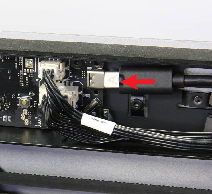
Unplugging the USB-C (#7) on the AP side can isolate the influence of the TH module on the AP, which can help us determine if the AP module itself is normal.
If the indicator on the AP board is still abnormal after unplugging the USB-C (#7) on the AP board, the problem is only in the AP module, that is, the AP board, the MC-AP cable, or the components on the AP, causing a short circuit, and you need to continue troubleshooting according to step 6.
If the indicator on the AP board returns to normal after unplugging the USB-C (#7) on the AP board, the problem is only in the TH module, that is, the TH board, the USB-C cable, or the components on the TH board, such as the heater, the cooling fan, or the motor, causing a short circuit. Then you need to continue troubleshooting according to step 7.
If the problem has been located in the AP module, you need to first unplug the chamber LED, camera, WiFi antenna, and button board (#1, #2, #3, #4) on the AP board, and observe whether AP board indicator light returns to normal.
If the AP indicator light is still abnormal, the AP board or the MC-AP cable pack needs to be replaced.
If the AP indicator light returns to normal, then with the power off, carefully plug in these connectors (#1, #2, #3, #4) one by one on the AP board. If plugging in a certain part causes the AP indicator light to become abnormal, that part needs to be replaced.
¶ Step 7: If after step 6, the problem has been located in the TH module, that is, the TH board assembly, the USB-C cable, or the parts on the TH board, such as the heater, the cooling fan or the motor, then we need to continue plugging and unplugging to isolate the specific faulty component.
Toolhead board assembly(V8) installation tutorial
Toolhead_boards_(V9) installation tutorial
If after unplugging connectors #2, #3, #4, #5, #8, #9, and #10 (while keeping the USB-C port, #1, and #7 connectors), the indicator lights on the TH board are still abnormal, it means the TH board assembly and the USB-C cable need to be replaced.
It should be emphasized again that when either end of the USB-C cable is disconnected, the indicator lights on the TH board will not light up, because the TH module requires a power supply through the USB-C connection.
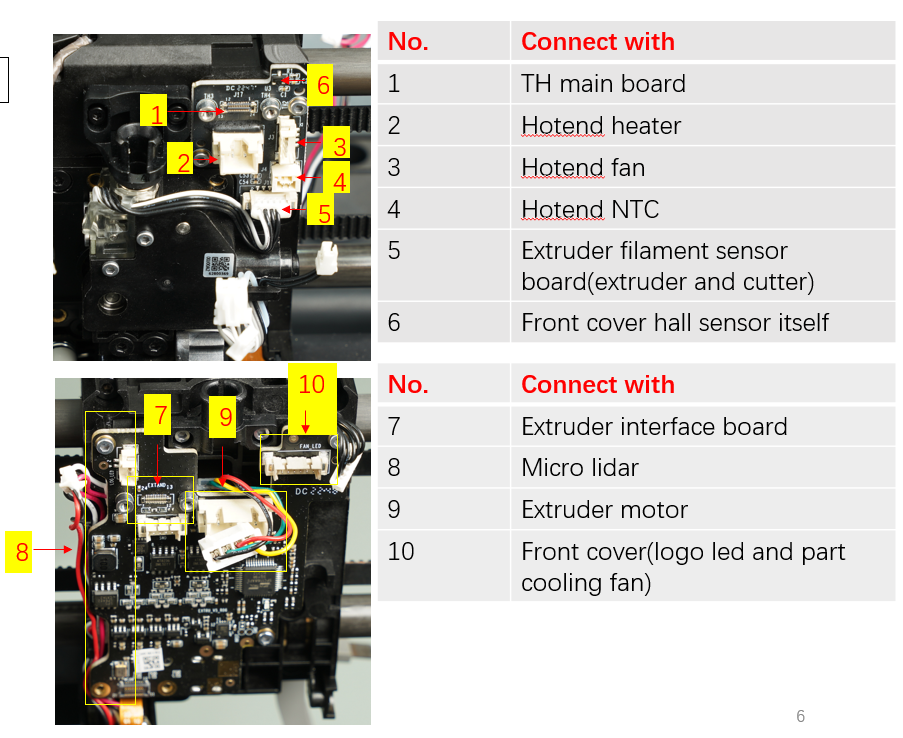
If after unplugging connectors #2, #3, #4, #5, #8, #9, and #10 (while keeping the USB-C port, #1, and #7 connectors), the indicator lights on the TH board return to normal, it means the TH components and the USB-C cable are working properly.
This means the problem may lie in one or more of the parts in connectors #2, #3, #4, #5, #8, #9, and #10. In this case, you need to reconnect these connectors (#2, #3, #4, #5, #6, #8, #9, #10) one by one with the power off to find the specific component causing the short circuit. If the TH indicator becomes abnormal after reconnecting a particular one, that component needs to be replaced.
¶ Step 8: As mentioned previously, if the issue has been isolated to the MC module, replacing the MC board is most likely to resolve the problem. However, if you want to be 100% certain, you can continue to investigate each 24V component on the MC board one by one, such as the plugs for the motors, fans, and AMS interface board.
If, after removing all the components on the MC board (including#1, #2, #3, #4, #5, #6, #7, #8, #9, #10, #11), the indicator lights on the MC board still do not illuminate, then we can be fairly certain that the MC board itself is faulty.

| NO. | Connect object | NO. | Connect object | NO. | Connect object |
|---|---|---|---|---|---|
| 1 | Motor Z | 5 | Auxiliary part cooling fan | 9 | AP main board (Power cable) |
| 2 | The right motor (view from the rear) | 6 | MC board fan | 10 | AP main board (Communication cable ) |
| 3 | The left motor (view from the rear) | 7 | MC board to AC board connecting cable | 11 | Heat bed (Communication cable) |
| 4 | The chamber temperature regulator fan | 8 | AMS interface board |
MC board installation tutorial
On the other hand, if after unplugging all the components on the MC board (including #1, #2, #3, #4, #5, #6, #7, #8, #9, #10, #11), the indicator on the MC board returns to normal, it means that a component on the MC board may be causing the short circuit.
In this case, you need to carefully reconnect these connectors on the MC board (including #1, #2, #3, #4, #5, #6, #7, #8, #9, #10, #11) one by one with the power off to identify the specific component causing the short circuit. If the MC indicator becomes abnormal after reconnecting a particular one, that component needs to be replaced.
In this step, you should pay special attention to the motors, fans (auxiliary fan, chamber temperature adjustment fan, and MC board fan), and AMS interface board on the MC board. These devices are powered by 24V and are more prone to causing short circuits in the circuit.
¶ End Notes
We hope the detailed guide provided has been helpful and informative.
To ensure a safe and effective execution, if you have any concerns or questions about the process described in this article, we recommend reaching out to technical support team before initiating the operation. We will do our best to respond promptly and provide the assistance you need. Click here to open a new ticket in our Support Page.