¶ Heat bed
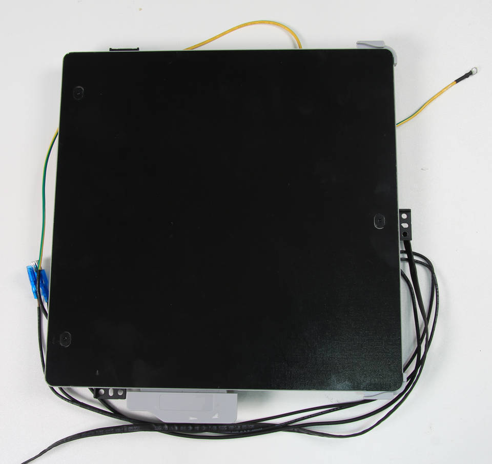
¶ Tools
H2.0/1.5 hex key
Tweezers
¶ Preparation
To prepare for the next steps, unplug the power cord cable.
¶ Video guide
This video guide is for the X1C V3 heatbed installation. Compared with X1C, replacing the P1P heatbed will be similar and simpler. So, you can refer to some steps in this video.
¶ Disassembly
¶ Step 1 - Remove the rear panel, excess chute, and the cable cover
Refer to the related contents of the Rear panel, Excess chute, and Cable cover to remove the rear panel, excess chute, and cable cover. (For P1S, you also need to remove the Right Plastic Panel Right Plastic Panel)
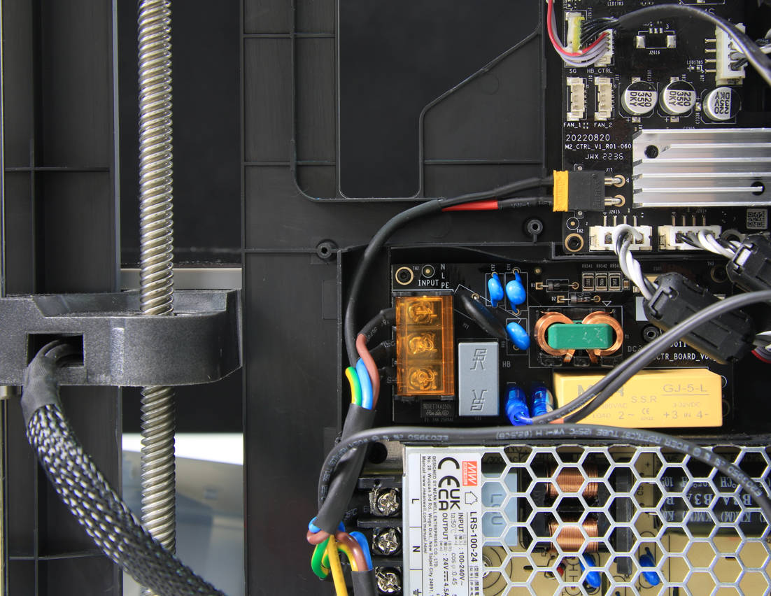
¶ Step 2 - Disconnect the heat bed power cable
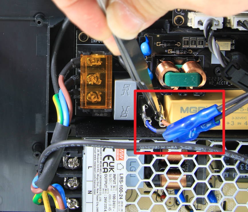
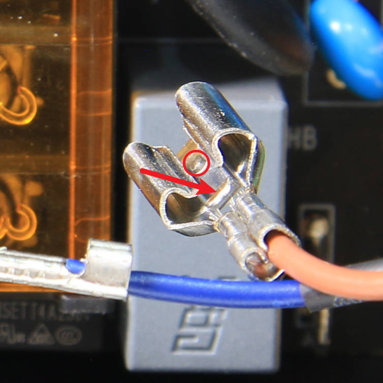
To remove the power cables, first, take off the protective rubber sleeve. Then, using tweezers, carefully release the locker and gently pull out the two power cables one at a time.
 |
 |
|---|
¶ Step 3 - Disconnect the heat bed signal cable
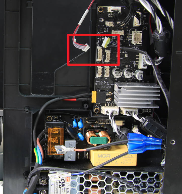
To disconnect the cables, start by carefully unplugging the MC-AC connection cable. Then, remove the silicone glue on the heat bed signal cable and carefully disconnect the signal cable.
¶ Step 4 - Remove the ground screw
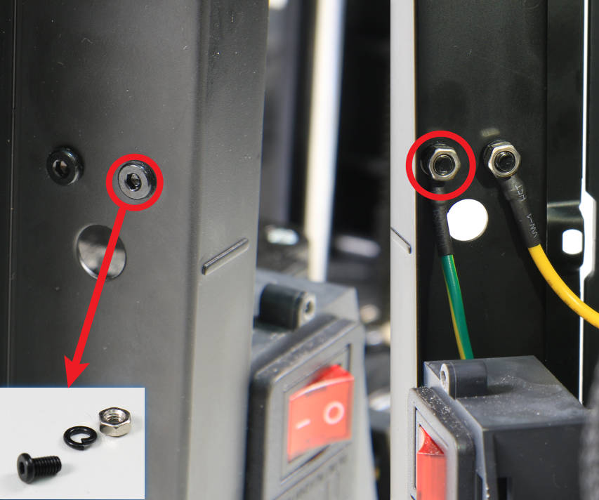
To loosen the ground cable, first press down on the nut with your hand. Then, using an H2.0 hex key, carefully unscrew the ground screw to release the cable.
¶ Step 5 - Release the cables
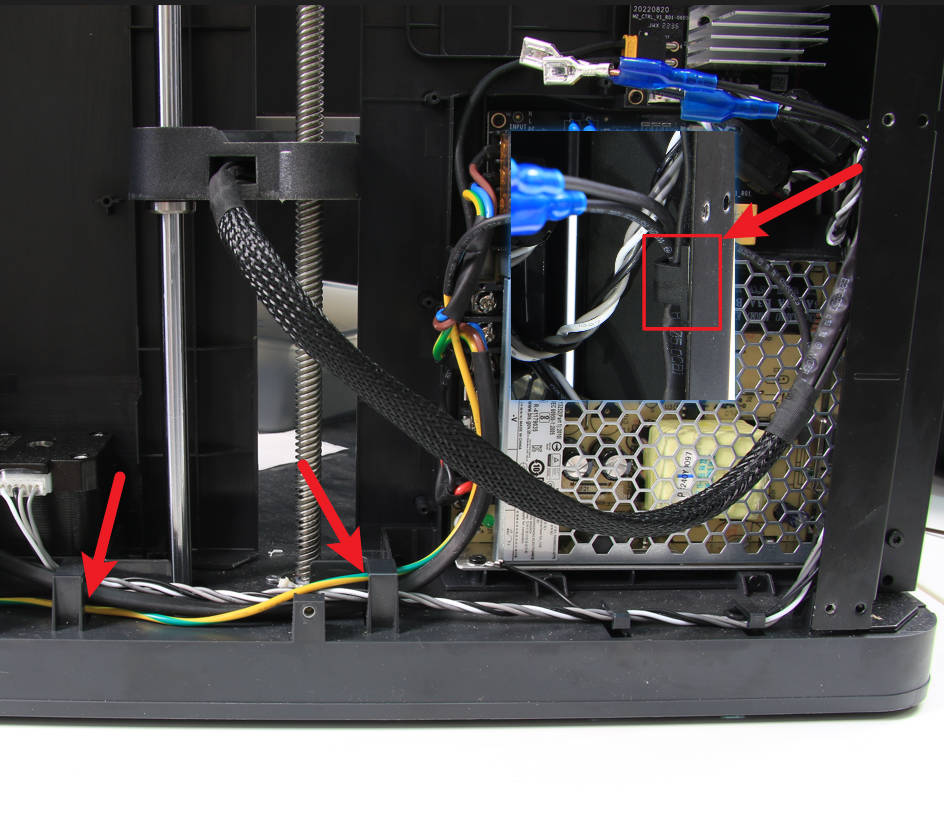
To remove the heat bed cables, carefully loosen them from the cable buckles/clips as shown in the image below.
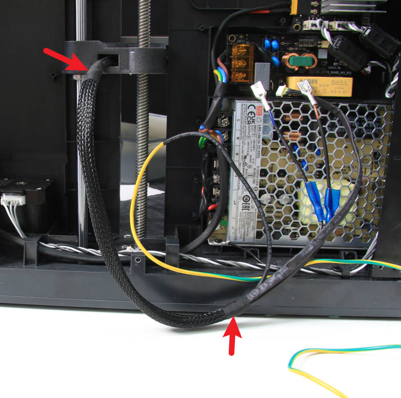
¶ Step 6 - Remove the cable mesh
To remove the cable mesh, carefully tear off the tapes at both ends of the mesh.
¶ Step 7 - Raise the heat bed
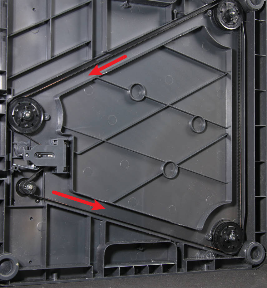
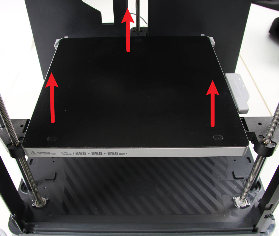
To prepare for the next steps, lay the printer on its right side and by pulling on the Z-axis belt to raise the heat bed to about 2/3 of its full height.
 |
 |
|---|
¶ Step 8 - Remove the holding plate
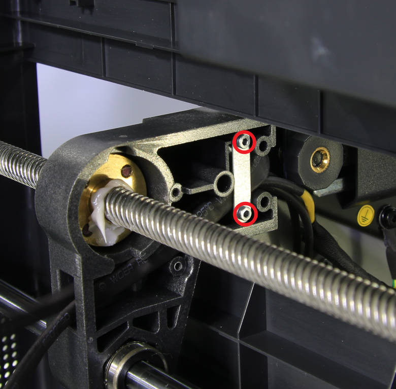
Unscrew 2 screws and remove the holding plate.
¶ Step 9 - Unlock the heat bed
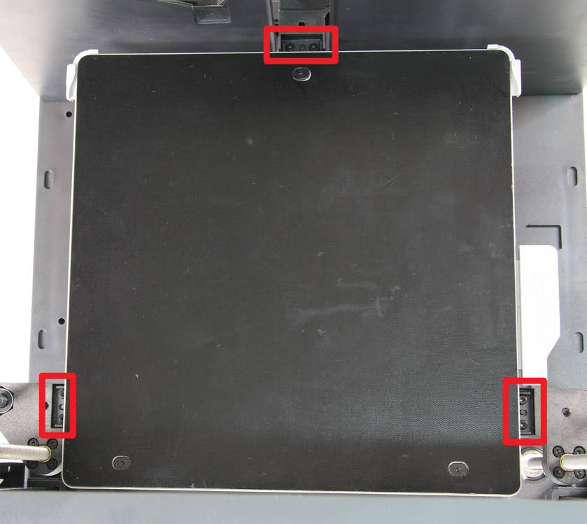
To remove the heat bed, first return the printer to an upright position. Then, use the hex key to carefully loosen the six screws that hold the heat bed in place and lift it away from the printer.
Please note that some screws might have a black sticker on them. You can safely remove the sticker, then proceed with the removal.
¶ Step 10 - Remove the heat bed
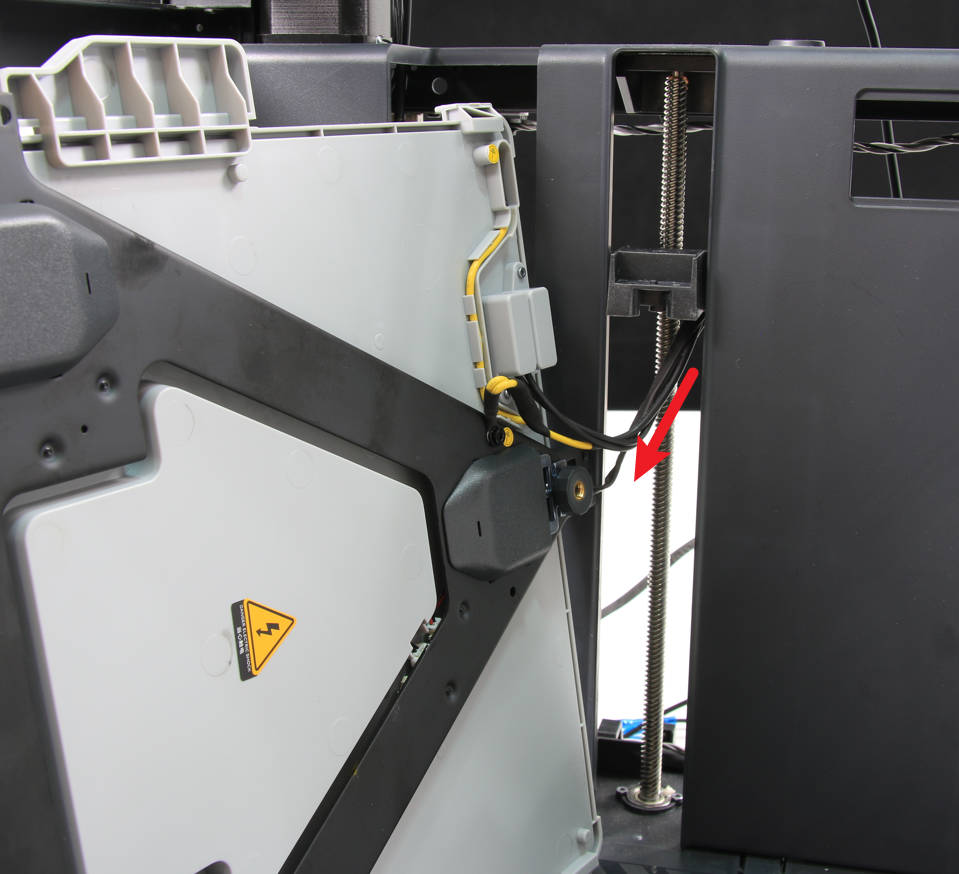
To remove the heat bed, lay it on its side as shown in the image below and gently pull out the heat bed cables. Then, carefully lift the heat bed away from the printer
¶ Assembly
¶ Step 1 - Installing the heat bed
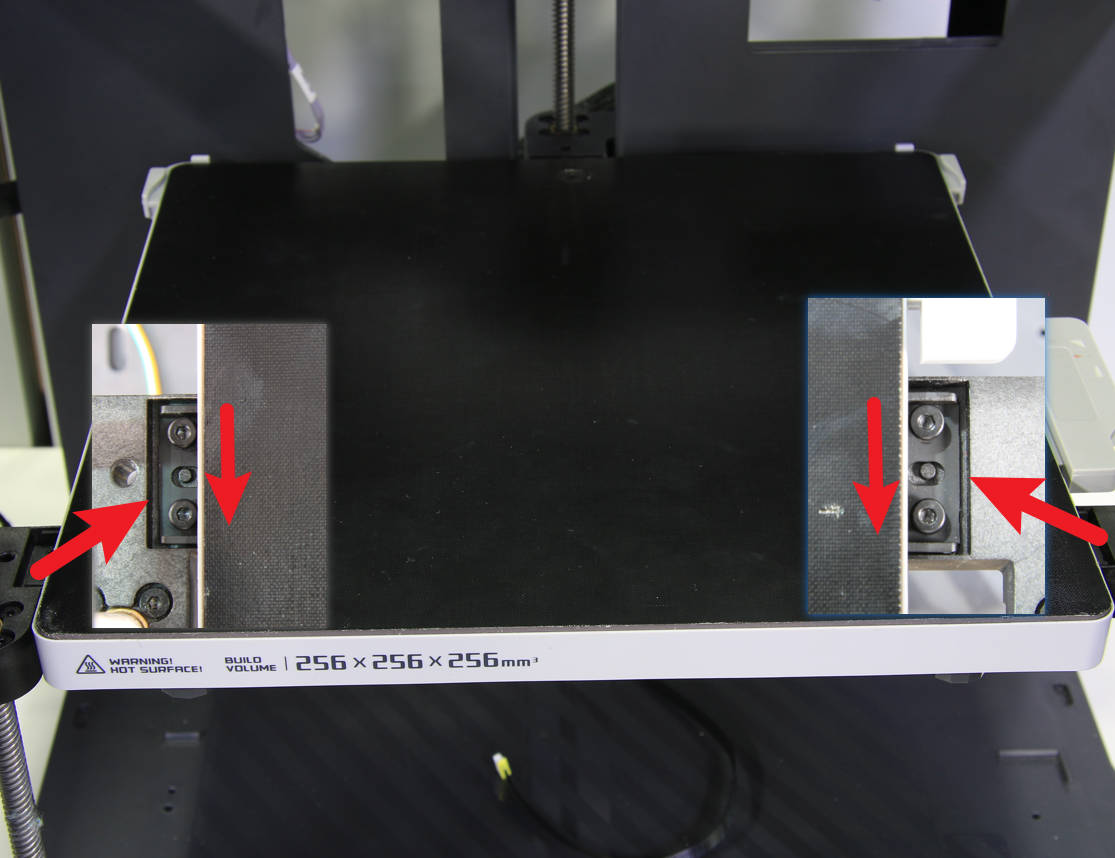
To install the heat bed, first, place it on the 3 Z-sliders and then slide the heat bed as far forward as possible. Once it is in position, use the hex key to carefully tighten the six screws to hold it in place.
 |
 |
|---|
¶ Step 2 - Pass through the heat bed cables, lock the holding plate
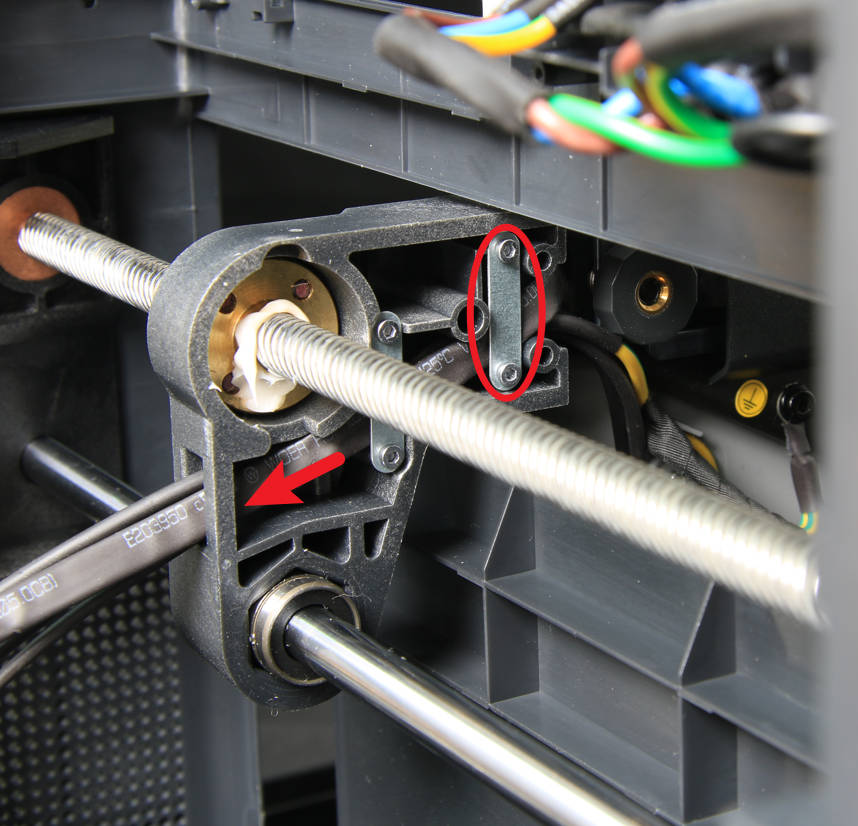
To install the printer, first, place it on its right side. Next, pass the heat bed cables through the cable hole on the rear slider. Make sure to arrange the cables and press them into the cable groove of the rear slider. Once the cables are in place, install the cable holding plate and secure it with two screws.
¶ Step 3 - Install the cable mesh
Install the cable mesh onto the cables, securing the ends with tape.

¶ Step 4 - Sort out the cables
To complete the installation, pass the ground cable through and position and secure the power cable and signal cable into the provided cable buckle/clip.

¶ Step 5 - Secure the ground cable
To secure the ground cable proceed to carefully reinstall the cable with the provided screw and nut.

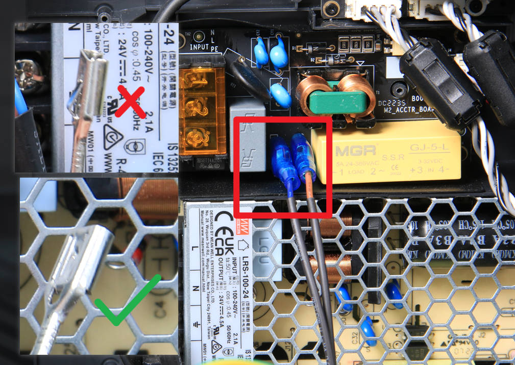
¶ Step 6 - Connect the power cable
check the status of the power cable plugs. Once they are confirmed, connect both plugs to the AC board connector. Finally, mount the protective sleeve to complete the process.
¶ Step 7 - Connect the signal cable
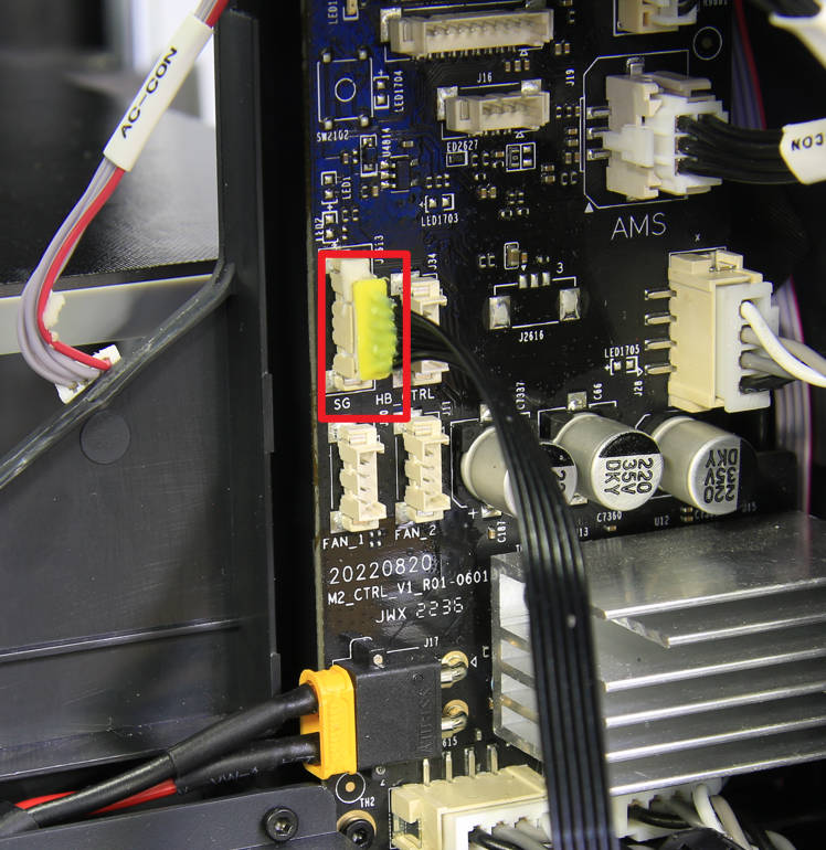
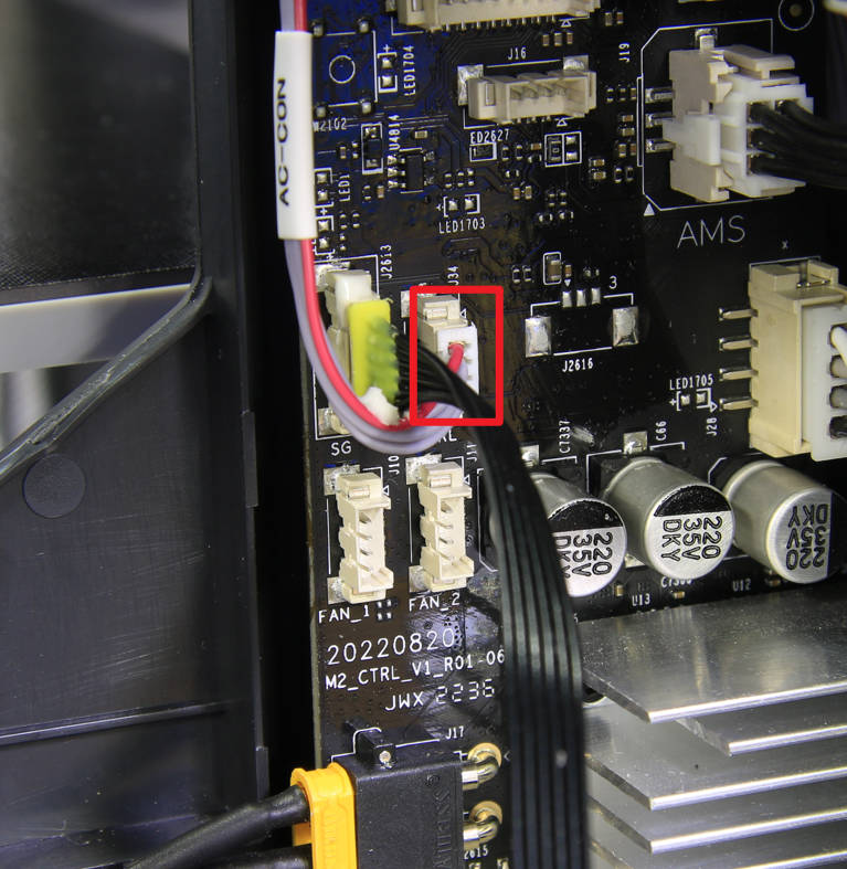
To connect the heat bed signal cable, attach it to the corresponding connector on the MC board. Then, apply silicone glue to the connector for added stability. Finally, connect the MC-AC connection cable to complete the process.
 |
 |
|---|
¶ Step 8 - Install the cable cover, excess chute, and the rear panel
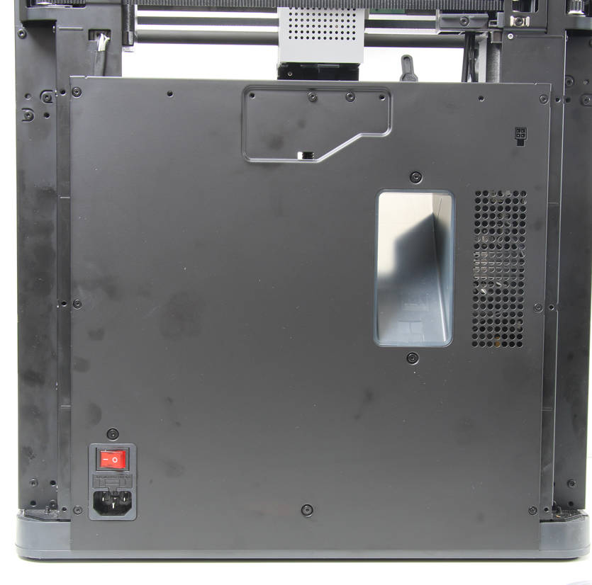
Refer to the related contents of the Cable cover, Excess chute, and Rear panel to install the cable cover, the rear panel, and the excess chute.
¶ How to verify
To finish the setup of the printer, connect the power cord cable.
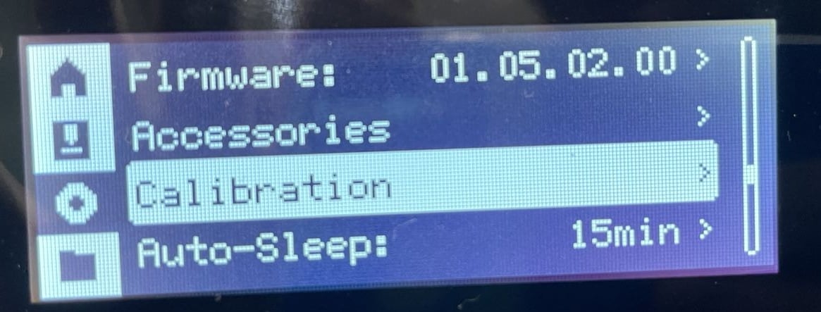
Power on the printer and initiate the device calibration process. If the calibration passes, the operation is successful.
