¶ Power Switch Assembly
¶ What it is
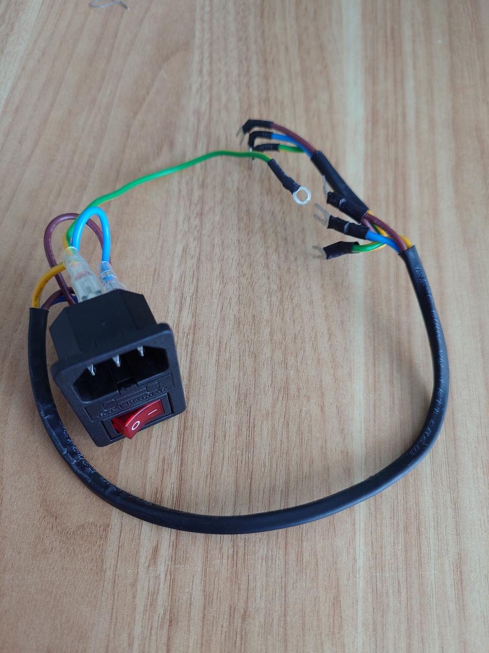
Power switch assembly is a module mounted in the lower left corner of the back of the printer. It contains a socket for the power cord, a switch to control the power for the printer and cables used to connect it to printer's power supply, AC board and ground.
¶ When to replace
- When the switch is damaged
- When the internal connection cable is damaged
- When the socket has poor contact
¶ Tools and materials needed
- New power switch assembly
- H1.5 H2.0 Allen key
- Phillips screwdriver
- Tweezers, pry bar or other flat tool
¶ Safety Warning
IMPORTANT!
It's crucial to power off the printer before performing any maintenance work on the printer and its electronics, including tool head wires, because leaving the printer on while conducting such tasks can cause a short circuit, which can lead to additional electronic damage and safety hazards.
When you perform maintenane or troubleshooting on the printer, you may be required to disassemble some parts, including the hotend. This process can expose wires and electrical components that could potentially short circuit if they come into contact with each other or with other metal or electronic components while the printer is still on. This can damage the electronics of the printer and cause further damage.
Therefore, it's essential to switch off the printer and disconnect it from the power source before doing any maintenance work. This will prevent any short circuits or damage to the printer's electronics. By doing so, you can avoid potential damage to the printer's electronic components and ensure that the maintenance work is performed safely and effectively.
If you have any concerns or questions about following this guide, open a new ticket in our Support Page and we will do our best to respond promptly and provide you with the assistance you need.
¶ Operation guide - Disassembly
Note: If you are an X1E user and need to replace the AC to power supply connection cable, please refer to the Wiki X1E Internal Power Supply Installation Tutorial at the same time.
¶ Step 1 - Disconnect the power cord
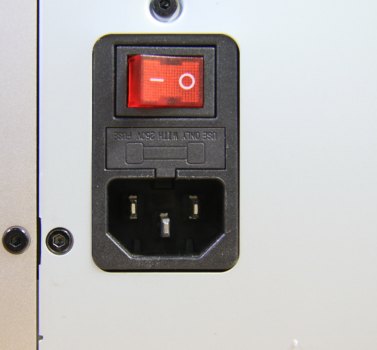
Disconnect the power cord from the power socket.
¶ Step 2 - Remove screws
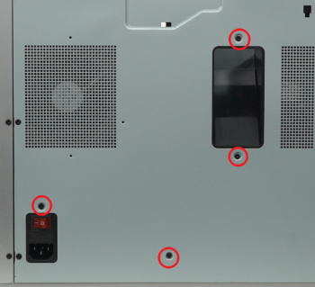
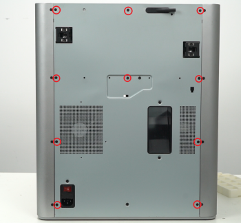
Remove the 10 fine tooth screws and 4 coarse tooth screws from the back cover as shown. These two types of screws are not to be mixed, so keep them separate so you don't get them mixed up.
 |
 |
¶ Step 3 - Remove rear cover
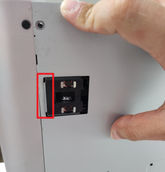
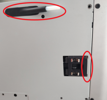
Remove the rear cover, unlock the left side belt tension ports first and then the right side one, to avoid getting stuck.
 |
 |
¶ Step 4 - Remove the excess chute
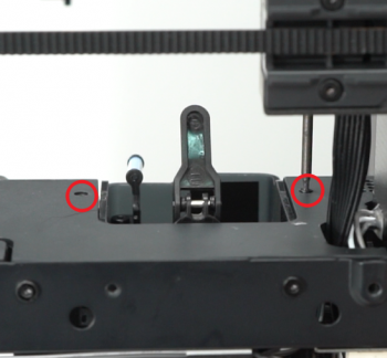
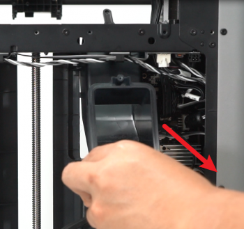
Remove 2 screws, and remove the excess chute.
 |
 |
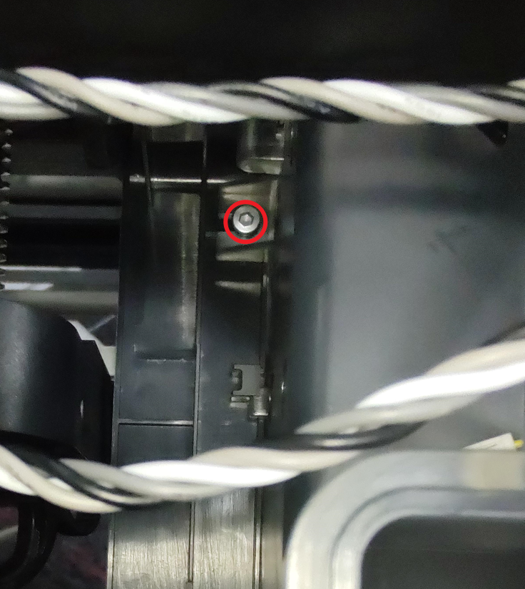
Note: Newer versions of the machine have 1 additional screw on the left side of the slide that can be unscrewed with a H2.0 wrench.
¶ Step 5 - Remove right side panel
Refer to this Wiki to remove the right side panel of the machine
¶ Step 6 - Remove the cable cover
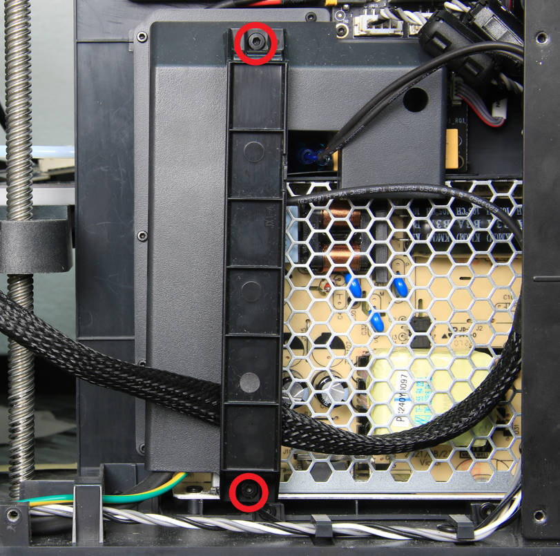
Remove the cable railing by removing the 2 screws with an H2.0 allen key.
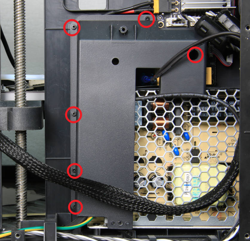
Remove 6 screws using H1.5 allen key, move the cable cover to the side.
 |
 |
¶ Step 7 - Disconnect the power cables from the power module and AC board
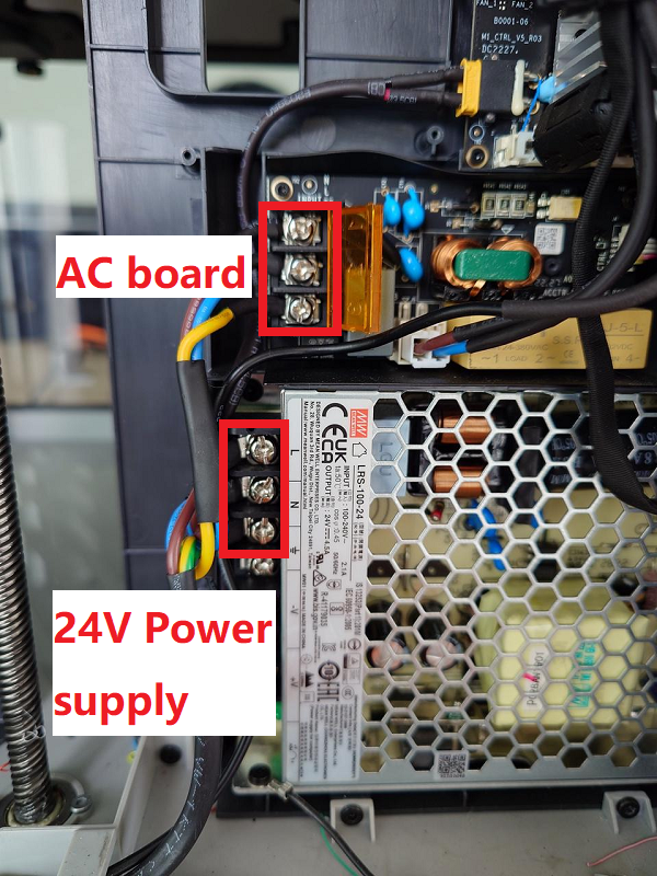
Use a Phillips screwdriver to loosen the 6 cables as shown in the image below and pull out to the left to disconnect them.
¶ Step 8 - Remove the ground wire
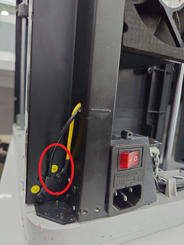
Remove the ground wire by loosening the ground wire retaining screw with an H2.0 wrench from the outside of the vertical beam near the power switch block.
Note: There are two ground wires fixed at the vertical beam, one for the whole machine ground (connected to the power switch block) and the other for the hot bed ground. Just loosen the whole machine grounding ground wire.
¶ Step 9 - Remove the Power Switch Module
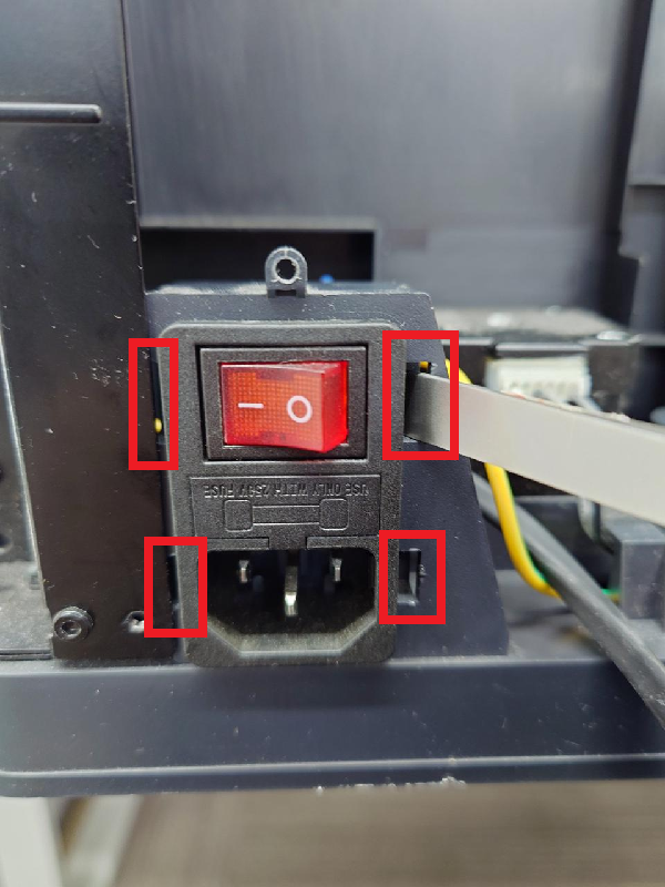
Use a flat tool to loosen the four tabs through the four openings in the frame on both sides of the power switch frame.
 |
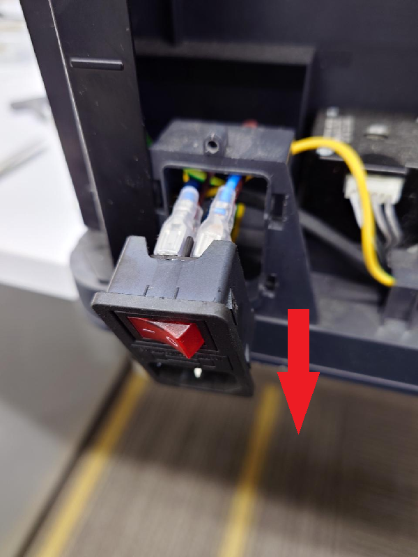 |
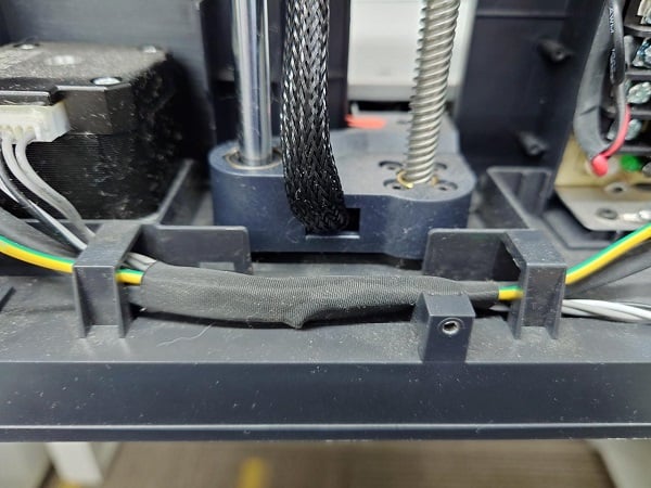
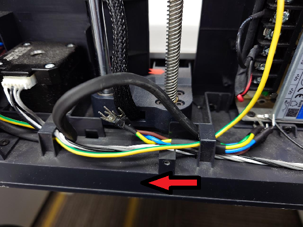
Remove the cable bundle tape and remove the cable that was disconnected in step 7 by threading it through the wire clips from right to left. The power switch assembly can then be removed along with the cable to complete disassembly.
 |
 |
¶ Operation guide - Assembly
¶ Step1 - Install power switch assembly
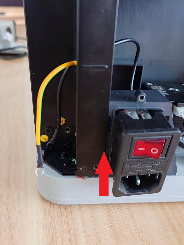
Feed all the cables of the new power switch assembly through the frame. Push the power switch assembly inward until all the tabs are in place and the assembly is firmly secured to its frame.
¶ Step 2 - Connecting the ground wire
Pass the ground wire through the vertical beam and then use an H2.0 wrench to secure it to the vertical beam.
Note: Grounding is an important measure to ensure electrical safety, so be sure to securely fix the ground wire.

¶ Step 3 - Connecting the Cable
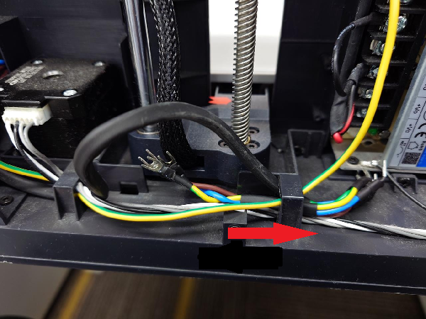
Thread the cables through the wire clips from left to right and apply the bundling tape. Use a Phillips screwdriver to secure the cable connector to the power supply module and AC board with Phillips screws.
NOTE: When connecting the top AC board, the wire sequence from top to bottom should be Neutral-Live-Ground, i.e., the colors are Blue-Brown-Yellow/Green. There are devices shipped with reversed neutral-live connection before August 2023 (as shown in the picture). Due to circuit protection this phenomenon has no effect on the function of the printer, but a trip will occur when connecting the printer to a polarity socket.
 |
 |
¶ Step 4 - Install the cable cover
Lock in 6 screws using H1.5 allen key to secure cable cover.
Install the cable railing by lock in 2 screws with an H2.0 allen key.
 |
 |
¶ Step 5 - Install side panel
Refer to this Wiki to install the right side panel.
¶ Step 6 - Install the excess chute
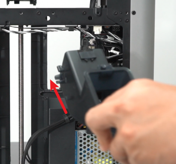
Install the excess chute, lock it in with 2 screws.
 |
 |
If the additional screw is removed from the side of the chute, remember to put it back.

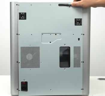
¶ Step 7 - Install the rear cover
Pass through the tube bracket and the right side belt tension port first to install the rear cover.
 |
 |
¶ Step 8 - Lock screws
Screw the back panel back on. Take note of the different types of screws used (10 fine tooth screws and 4 coarse tooth screws).
 |
 |
¶ Verify the functionality
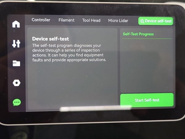
Connect the power cord and turn power ON. Start a self-test. If no errors occur, the replacement is completed successfully.
¶ End Notes
We hope that the detailed guide we shared with you was helpful and informative.
We want to ensure that you can perform it safely and effectively. If you have any concerns or questions regarding the process described in this article, we encourage you to reach out to our friendly customer service team before starting the operation. Our team is always ready to help you and answer any questions you may have.
Click here to open a new ticket in our Support Page.
We will do our best to respond promptly and provide you with the assistance you need.