¶ X1E Internal Power Supply
Due to product changes, X1E has changed the power module, increased the power, and added a cooling fan.
This page provides the relevant guidelines for disassembling and assembling the X1E internal power supply and explains the relevant precautions. You can also refer to this page for disassembling and assembling the replaceable parts involved in this process.
¶ Parts List
Associated Parts List
| NO. | Descriptions | Pics | NO. | Descriptions | Pics |
| 1 | X1E Rear Metal Panel |
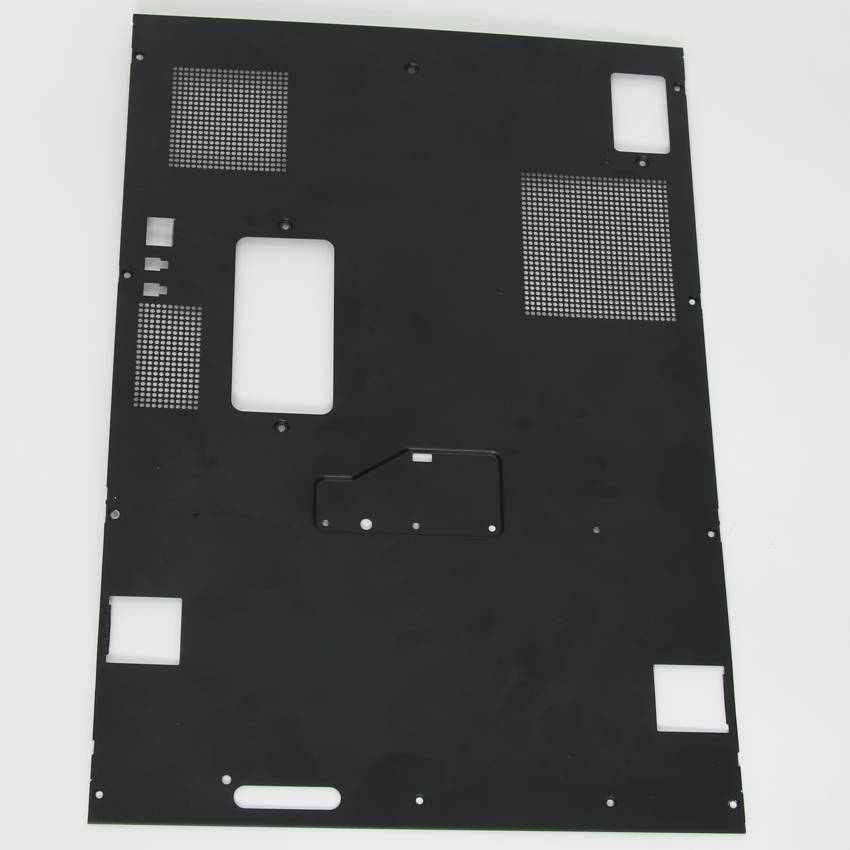
|
2 | Excess chute |
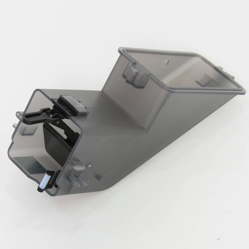 |
| 3 | Chamber Temperature Regulator fan |
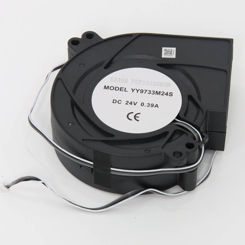 |
4 | Network Interface and AMS Connection Board |
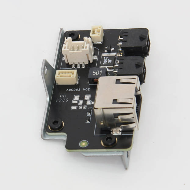 |
| 5 | Power Cooling Fan |
 |
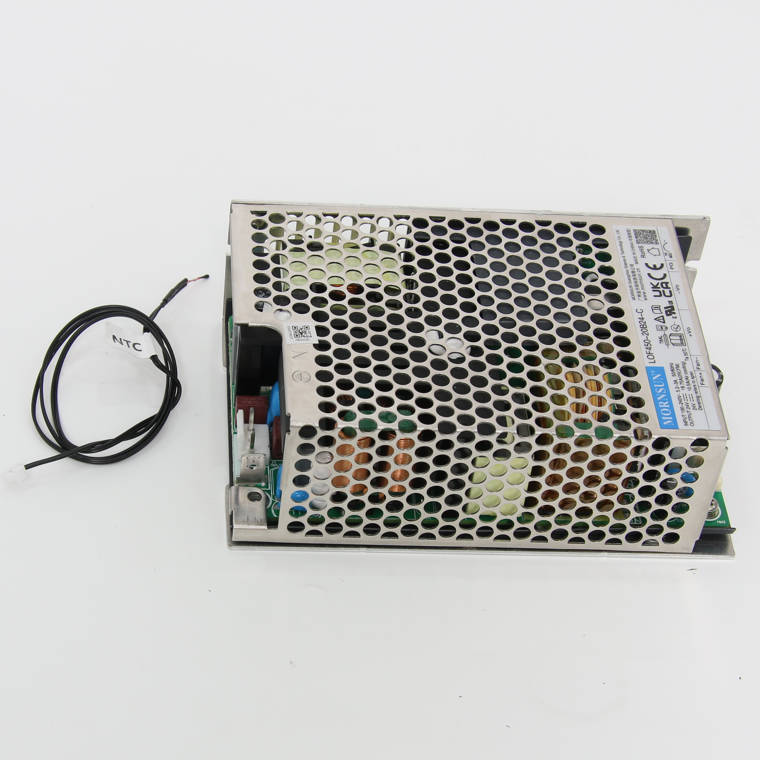
6 | Internal Power Supply (24V 450W) |
 |
| 7 |
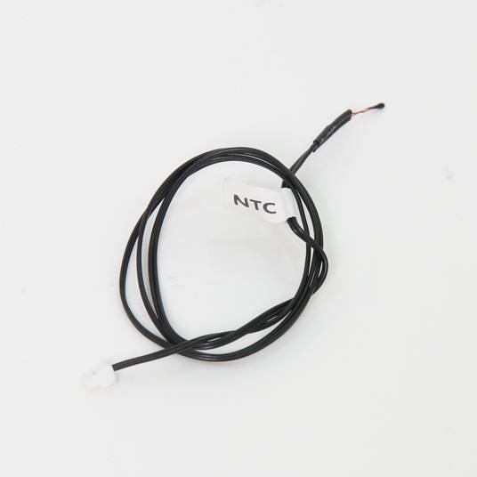
NTC for power supply (Cable pack) |
 |
¶ Screws List
| Model | Position | Drawing | Model | Position | Drawing | ||
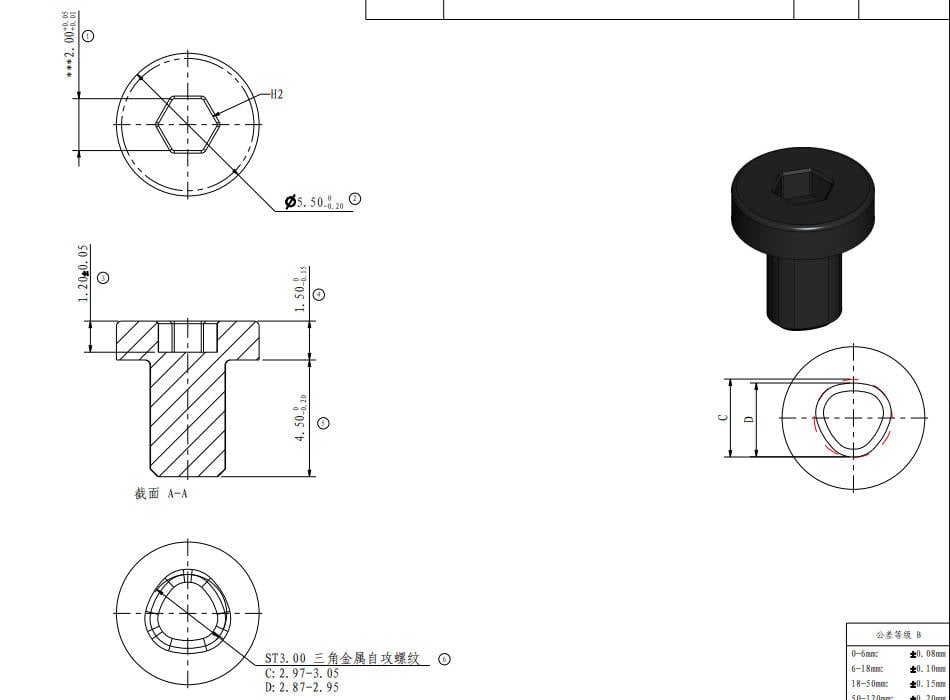
| Screw A | ST3*4.5 |
Rear panel (9PCS) |
 |
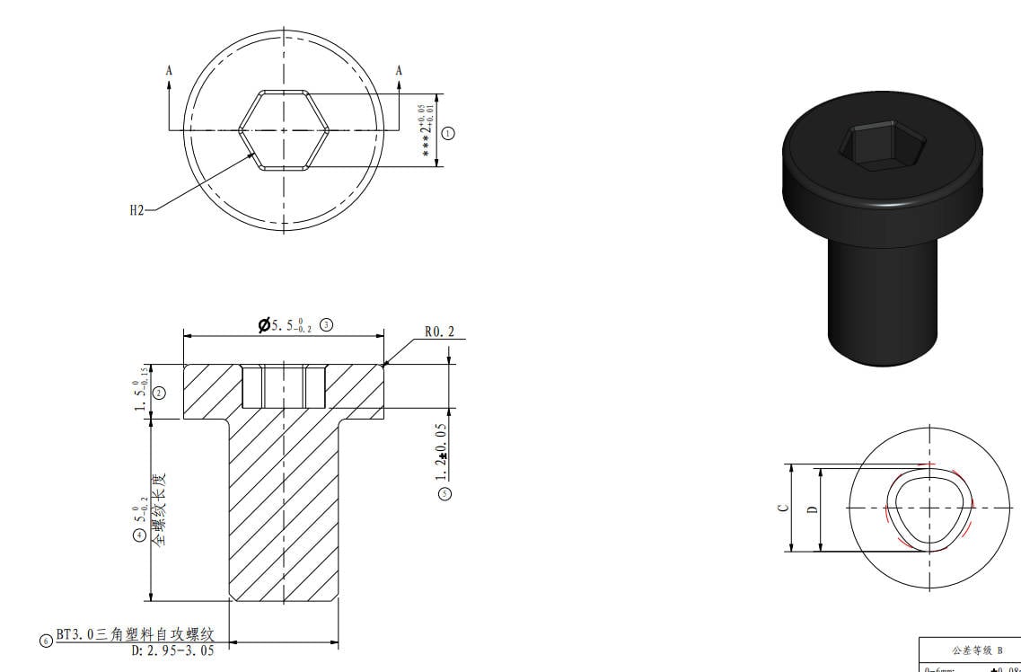
Screw B |
BT3*5
|
Rear panel,Air duct (4PCS/3PCS) |
 |
| Screw C | M3*4.5 |
Rear panel (1PCS) |
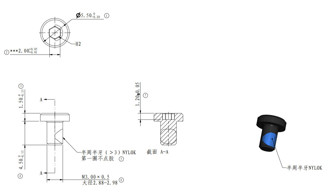
|
Screw D | BT2*8 |
Excess chute、Power protective cover (2PCS/ 7PCS) |
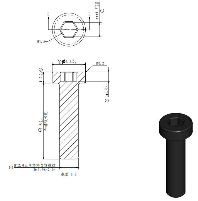 |
| Screw E | BT2*5 |
Excess chute (1PCS) |
/
|
Screw F | BT3*8 | Fan,AMS Connection Board(1PCS/1PCS) |
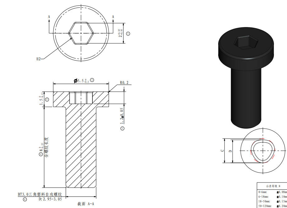 |
| Screw G | BT2*6 |
Power cooling Fan (3PCS) |
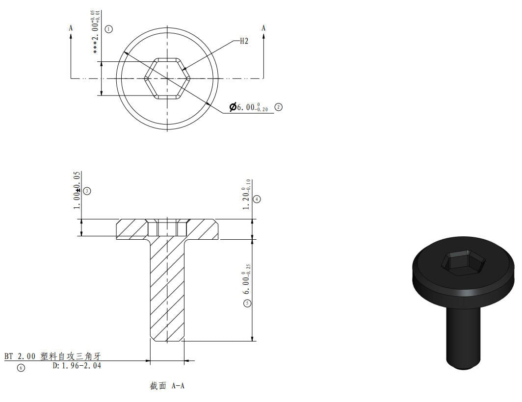 |
Screw H | M3*6 |
Power supply, AMS Connection Board (4PCS/2PCS) |
 |
¶ Tools and materials needed
H1.5 /H2.0 hex key
Cross screwdriver
¶ Safety Warning
IMPORTANT!
It's crucial to power off the printer before performing any maintenance work on the printer and its electronics, including tool head wires, because leaving the printer on while conducting such tasks can cause a short circuit, which can lead to additional electronic damage and safety hazards.
When you perform maintenane or troubleshooting on the printer, you may be required to disassemble some parts, including the hotend. This process can expose wires and electrical components that could potentially short circuit if they come into contact with each other or with other metal or electronic components while the printer is still on. This can damage the electronics of the printer and cause further damage.
Therefore, it's essential to switch off the printer and disconnect it from the power source before doing any maintenance work. This will prevent any short circuits or damage to the printer's electronics. By doing so, you can avoid potential damage to the printer's electronic components and ensure that the maintenance work is performed safely and effectively.
If you have any concerns or questions about following this guide, open a new ticket in our Support Page and we will do our best to respond promptly and provide you with the assistance you need.
¶ Disassembly
¶ Step 1: Remove the Rear Panel
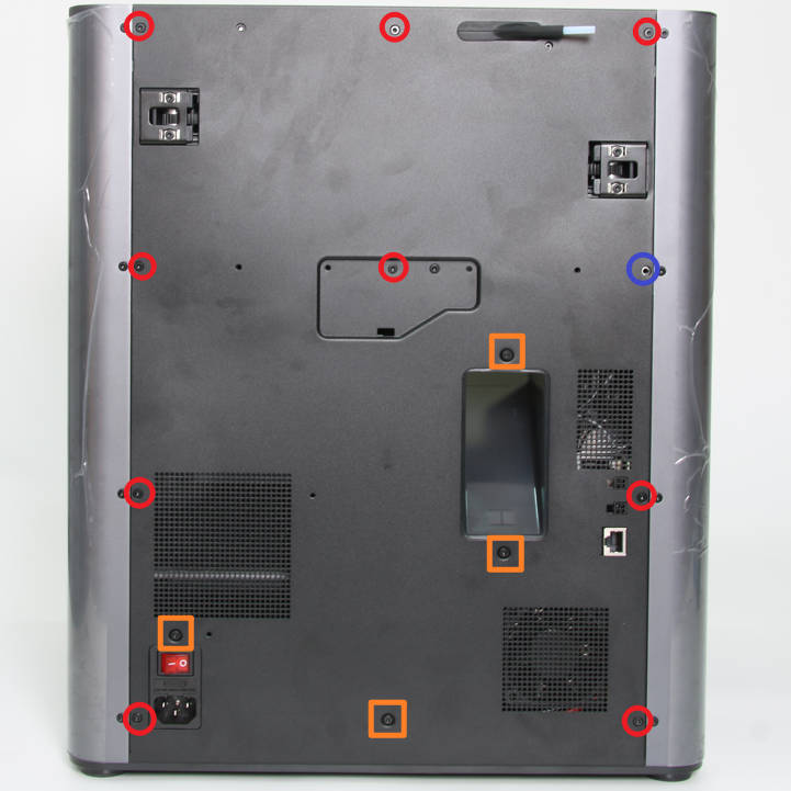
Remove the glass cover, and then as shown in Figure 1-1-1, remove 9 screws A, 4 screws B, and 1 screw C with the H2.0 hex key;
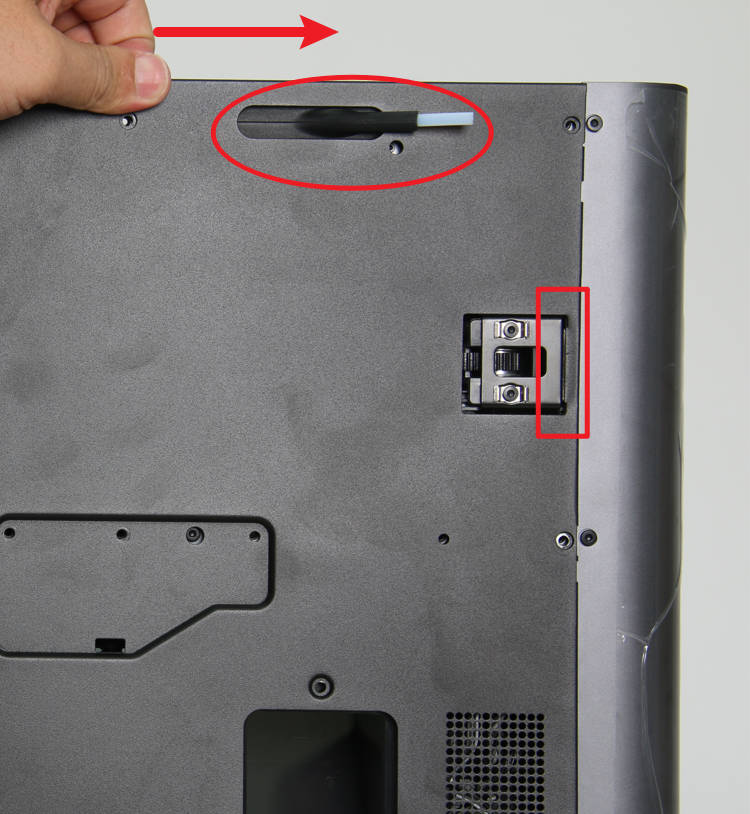
As shown in Figure 1-1-2, first push the rear panel to the right a little bit, and loosen the rear panel from the tensioner on the right side;
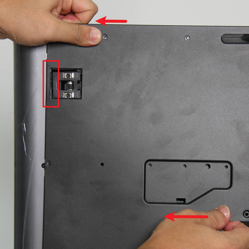
As shown in Figure 1-1-3, apply force to the left, release the rear panel from the left tensioner, and remove the rear panel.
|
|
|
¶ Step 2: Remove the Excess Chute
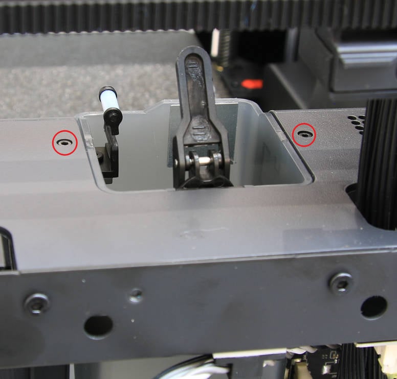
As shown in Figure 1-2-1, remove the 2 screws D with the H1.5 hex key;
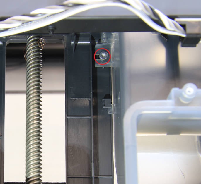
As shown in Figure 1-2-2, remove 1 screw E with the H2.0 hex key;
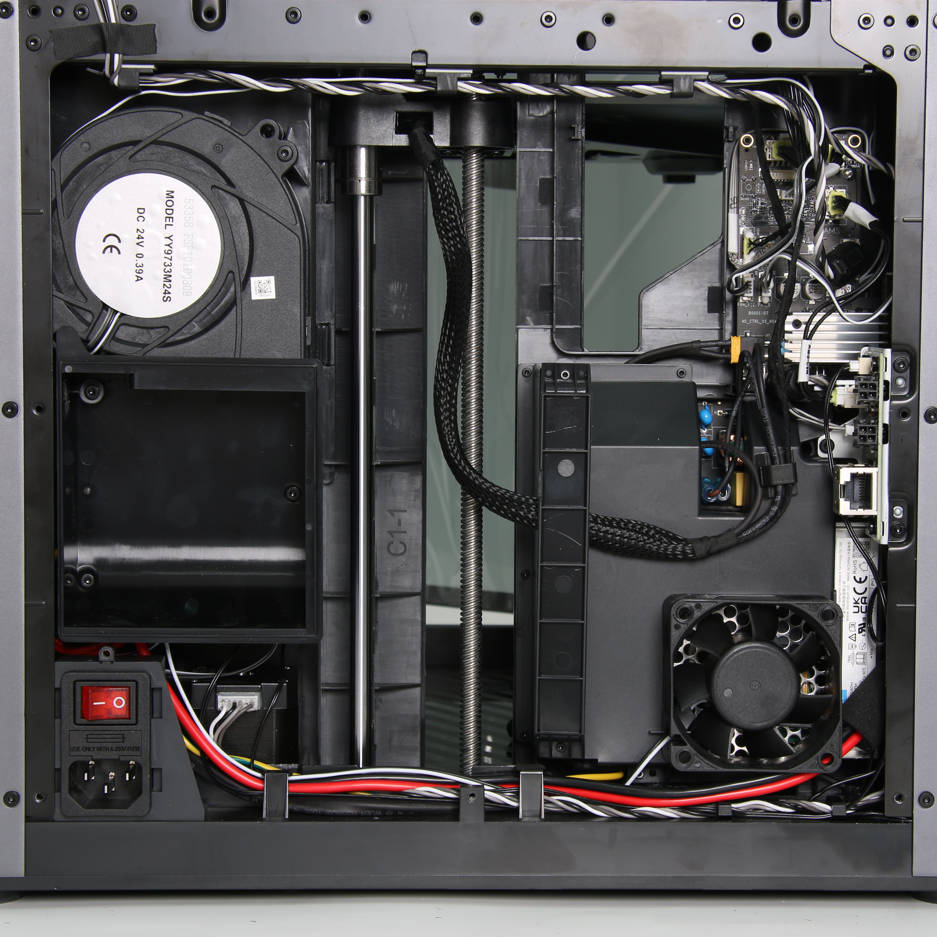
Remove the excess chute, as shown in Figure 1-2-3.
|
|
|
¶ Step 3: Remove the Chamber Temperature Regulator Fan
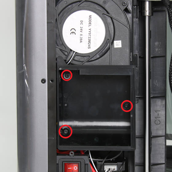
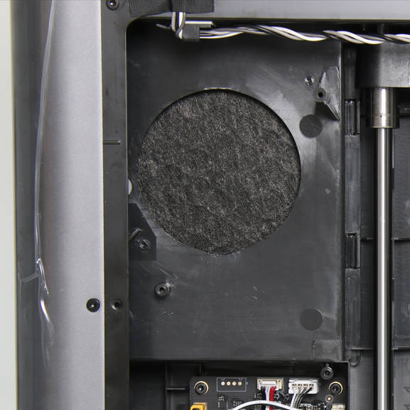
As shown in Figure 1-3-1, remove the 3 screws B with the H2.0 hex key and remove the air duct;
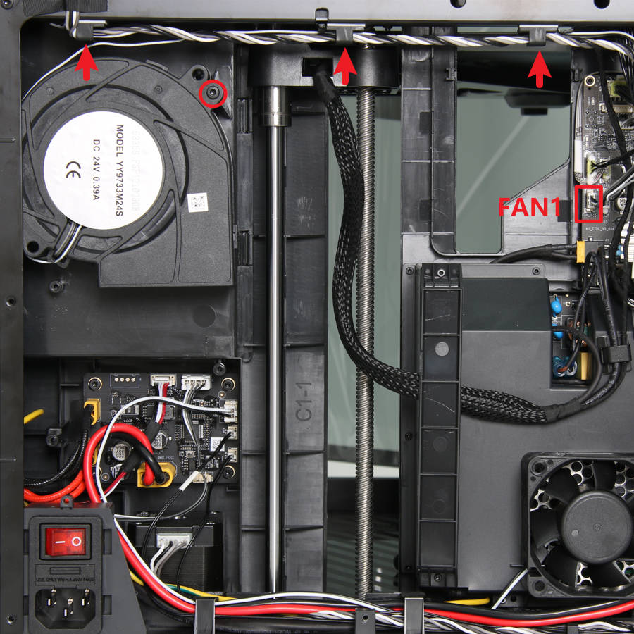
As shown in Figure 1-3-2, disconnect the fan connection from the interface labeled FAN1 on the main control board, loosen the fan cable from the three cable ties, and remove 1 screw F with the H2.0 hex key;
Remove the chamber temperature regulator fan, as shown in Figure 1-3-3.
(You only need to remove the air duct when replacing the power supply)
|
|
|
¶ Step 4: Remove the Network Interface and AMS Connection Board
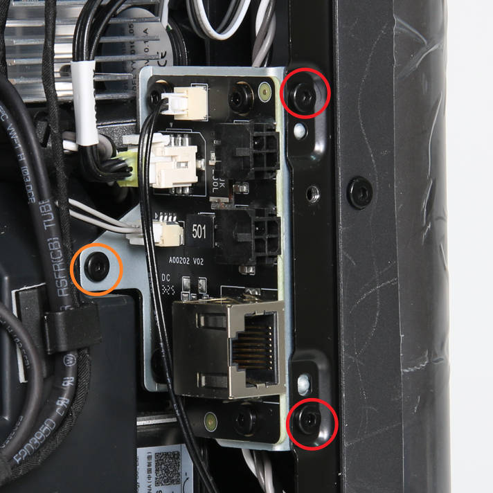
As shown in Figure 1-4-1, remove 2 screws G and 1 screw F with the H2.0 hex key to loosen the board with the holder plate;
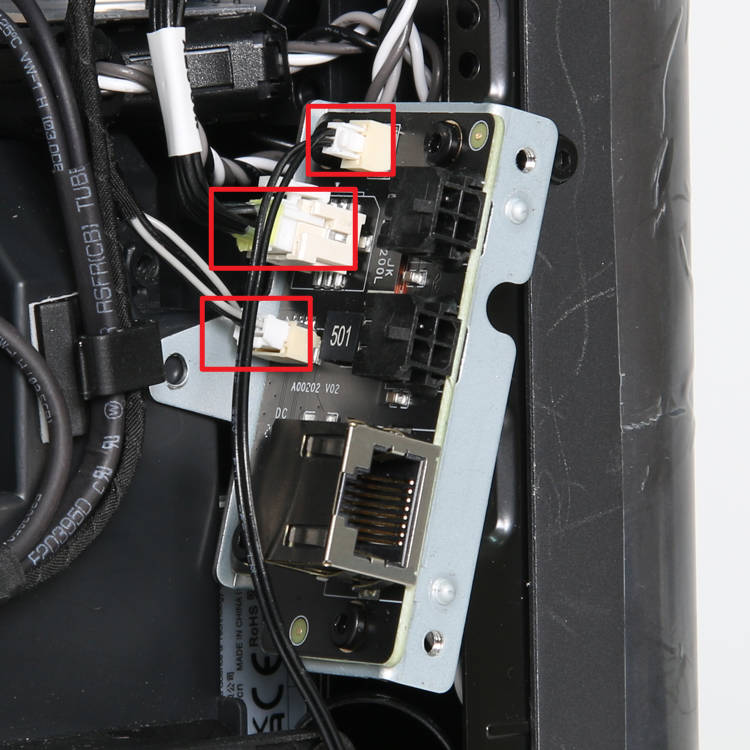
As shown in Figure 1-4-2, disconnect the three connectors and remove the network interface and AMS connection board;
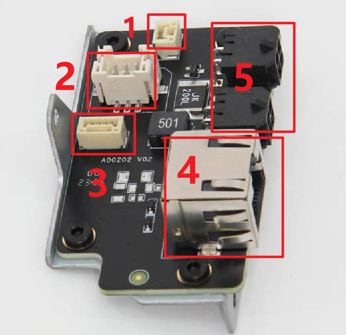
As shown in Figure 1-4-3, the numbered connectors are connected to the following objects:
1- Chamber Heater Control Board 2- MC board 3- Network Interface Board 4- Network Cable 5- AMS
|
|
|
¶ Step 5: Remove the Power Cooling Fan
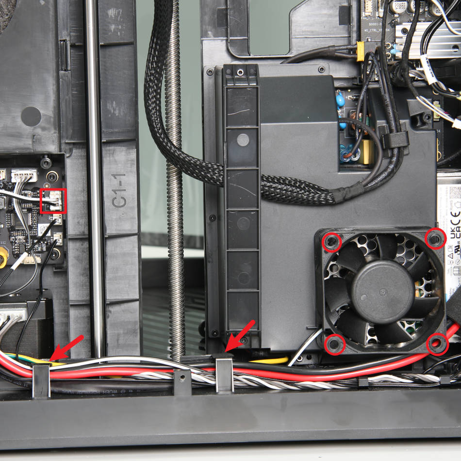
As shown in Figure 1-5-1, disconnect the power cooling fan cable from the chamber heater control board, remove 4 screws G, and take off the power cooling fan.
¶ Step 6: Remove the Internal Power Supply
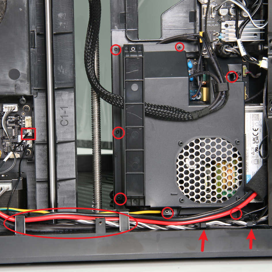
As shown in Figure 1-6-1, disconnect the power supply NTC cable from the heater control board, loosen the NTC cable from the cable buckles on the base, remove 7 screws D with an H1.5 hex key, and open the power protective cover;
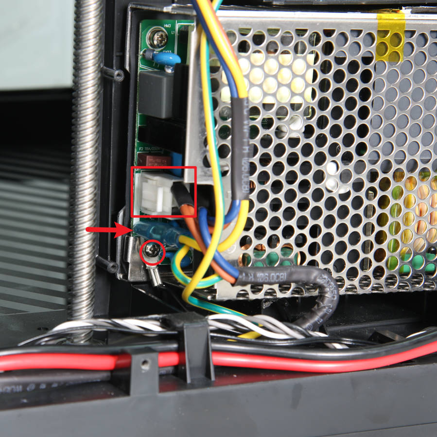
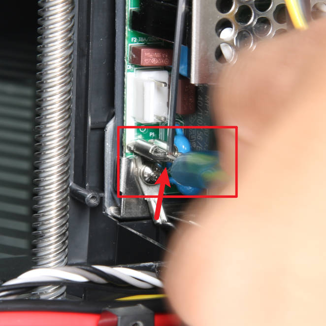
As shown in Figure 1-6-2 and Figure 1-6-3, disconnect the input cable of the power supply, remove the rubber sleeve on the ground plug, press to unlock the plug and remove the socket, and loosen 1 screw with a cross screwdriver to disconnect the black ground cable;
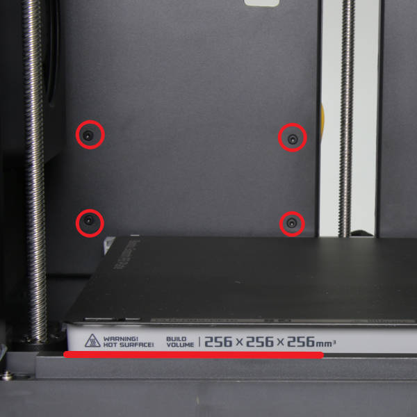
As shown in Figure 1-6-4, by pulling the Z-axis belt, lower the heatbed to the bottom, and remove the 4 screws H use the H2.0 hex key;
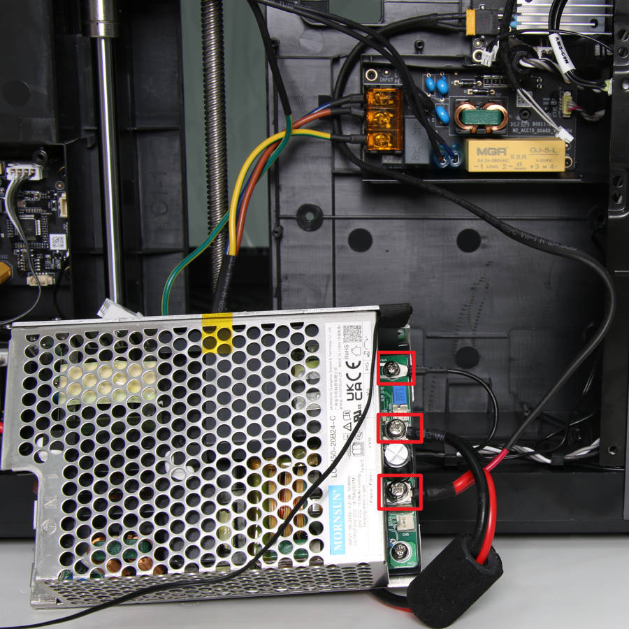
As shown in Figure 1-6-5, take out the power supply, loosen 3 screws with a cross screwdriver, remove the power cord of the heater module, the power cord of the MC board and its ground cable, and then remove the power supply;
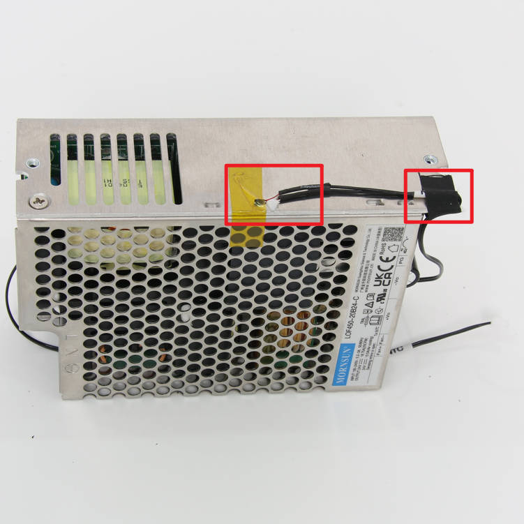
As shown in Figure 1-6-6, remove the tape and white glue, and the NTC can be removed from the power supply (This operation is only required when replacing the NTC ).
|
|
|
|
|
|
¶ Assembly
¶ Step 1: Install the Internal Power Supply
As shown in Figure 2-1-1, install the NTC resistor on the power supply and fix it with adhesive tape or silicone gel;
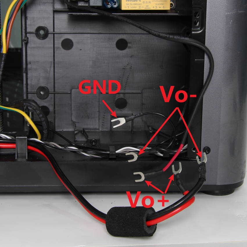
As shown in Figure 2-1-2 and Figure 2-1-3, connect the power cables of the MC board and the heater control board to the output terminals of the power supply, the red cables should be connected to Vo+, and the black one ones connected to Vo-, and then lock the terminal screws, connect the ground cable to the screw in the upper right corner, and tighten the screw;
As shown in Figure 2-1-4, confirm that the power supply is installed in place from the inside of the chamber, and lock in 4 screws H to fix it;
As shown in Figure 2-1-5, connect the input cables, connect two ground cables, tighten the screw and push the rubber sleeve in place, and the connect the power input plug;
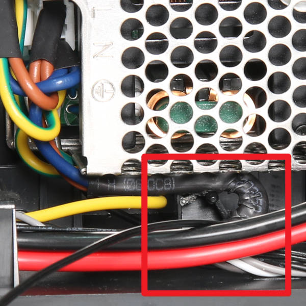
As shown in Figure 2-1-6, connect the NTC cable to the connector of the heater control board, arrange the cable into the buckles, install the power protective cover, and lock in 7 screws D to fix it.

|
|

|

|

|

|
Note: Before installing the power protective cover, please check the installation position of the power cord and avoid the screw hole, as shown in Figure 2-1-7.
¶ Step 2: Install the Power Cooling Fan
As shown in Figure 2-2-1, install the cooling fan of the power supply. Note that the outlet direction of the fan cable should be in the lower left corner. Lock in 4 screws G to fix it. Then connect the fan to the control board of the heating module, and then arrange the fan cable. Insert it into the cable buckles.

¶ Step 3: Install the Network Interface and AMS Connection Board
As shown in Figure 2-3-1, the numbered connectors are connected to the following objects:
1- Chamber Heater Control Board 2- MC board 3- Network Interface Board 4- Network Cable 5- AMS
As shown in Figure 2-3-2, according to the descriptions of the above interfaces, connect the 3 connectors in sequence;
As shown in Figure 2-3-3, install the network interface and AMS connection board, and lock in 2 screws H and 1 screw F.
|

|

|

|
¶ Step 4: Install the Chamber Temperature Regulator Fan
As shown in Figure 2-4-1, install the chamber temperature regulator fan, fix the fan with 1 screw F, then arrange the fan cable into the cable buckles along the route indicated by the arrow in the figure, and finally connect it to the MC board connector marked with FAN1;
As shown in Figure 2-4-2, install the air duct under the chamber temperature regulator fan, and lock in 3 screws B to fix it.

|

|
¶ Step 5: Install the Excess chute
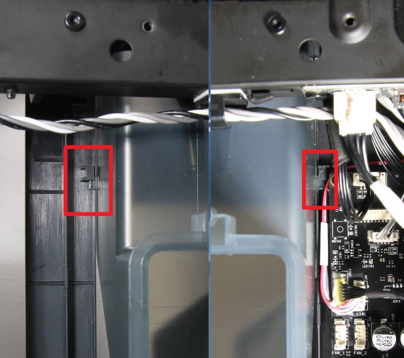
As shown in Figure 2-5-1, install the excess chute to the printer, the buckles on both sides of the chute should slide into place, and confirm that the connecting cables are not pressed;
As shown in Figure 2-5-2, lock 1 screw E on the left side of the chute;
As shown in Figure 2-5-3, lock 2 screws D on the top of the chute.
|

|

|
¶ Step 6: Install the Rear Panel
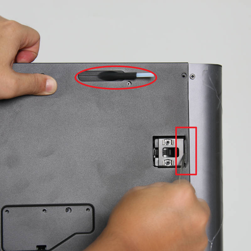
As shown in Figure 2-6-1, first pass the tube bracket through the rear panel, and then install the part near the tensioner on the right side in place, you can the hex key to press the edge to install it;
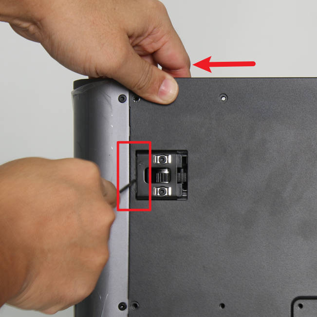
As shown in Figure 2-6-2, pull the rear panel to the left and install the part near the left tensioner in place, you can use the hex key to press the edge to assist in the installation;
As shown in Figure 2-6-3, lock in 9 screws A, 4 screws B and 1 screw C to fix the rear panel.
|
|

|
¶ Verify the functionality
1. Connect the AMS to the printer, and start up the printer, confirm that the printer and AMS can start normally;
2. Operate on the screen, click the chamber temperature regulator fan icon, then turn on the fan, confirm that the fan can be turned on and off normally;
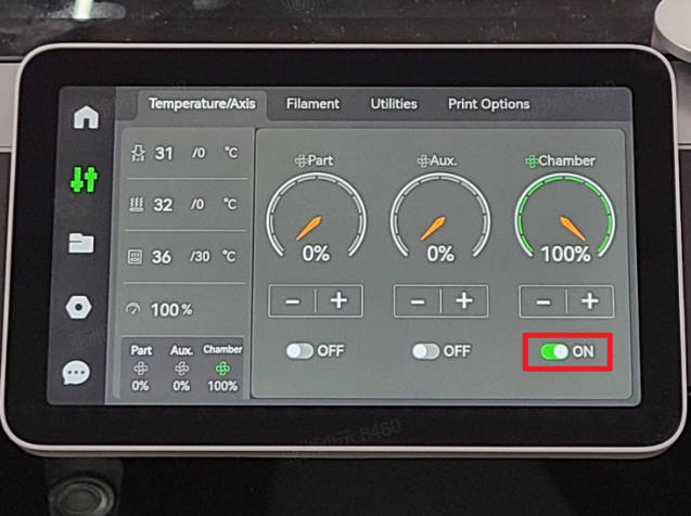
3. Operate on the screen, tap the chamber temperature icon, set the temperature higher than the current one, and confirm that the cooling fan of the power supply and the heater fan can start to work.
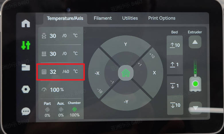
If the test fails, please check all connections again and try again. If that still doesn't work, please contact the Bambu Lab service team.
¶ Calibration step after the operation
There is no need to perform any calibration or operation before using the printer after the related parts replacement on this page.
¶ End Notes
We hope that the detailed guide we shared with you was helpful and informative.
We want to ensure that you can perform it safely and effectively. If you have any concerns or questions regarding the process described in this article, we encourage you to reach out to our friendly customer service team before starting the operation. Our team is always ready to help you and answer any questions you may have.
Click here to open a new ticket in our Support Page.
We will do our best to respond promptly and provide you with the assistance you need.