¶ Introduction
Modifier is a special type of object used to modify parameters within the overlapping parts of a model or within a specified height range.
¶ When to use
For example:
- When printing a model with a high height, you can use the height range modifier to slow down the printing of the upper part of the model, thus preventing it from collapsing during the printing process.
- To strengthen some of the weaker parts of the model, adjust the infill density of the corresponding areas to make them stronger.
- If you need to add flat text to the surface of the model, use the modifiers to do so.
If you want to add a concave text to your model, please refer to: Negative Part
If you want to add a raised text, please refer to: 3D Text
¶ Height Range Modifier
¶ Modify the print speed for a specified height range
Step 1. Right-click the model and select Height range Modifier from the menu.
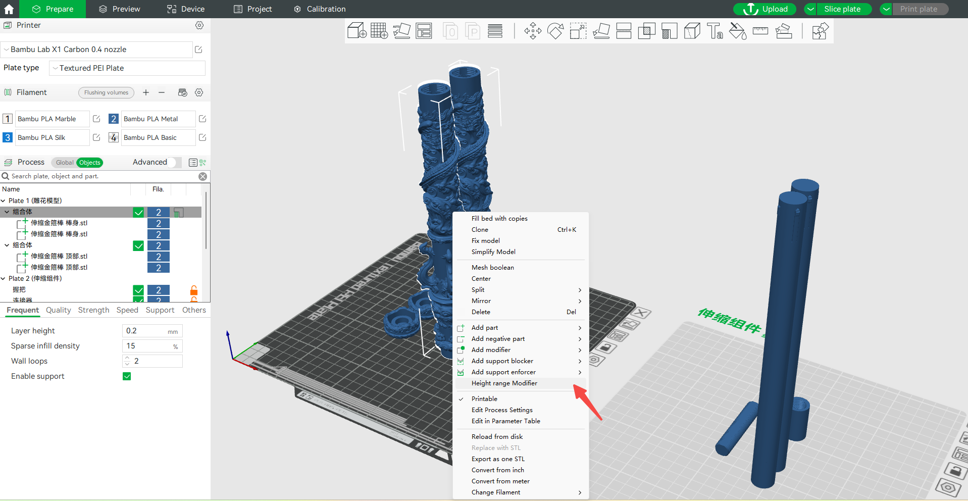
Step 2. Click Range to set the specified model height range.
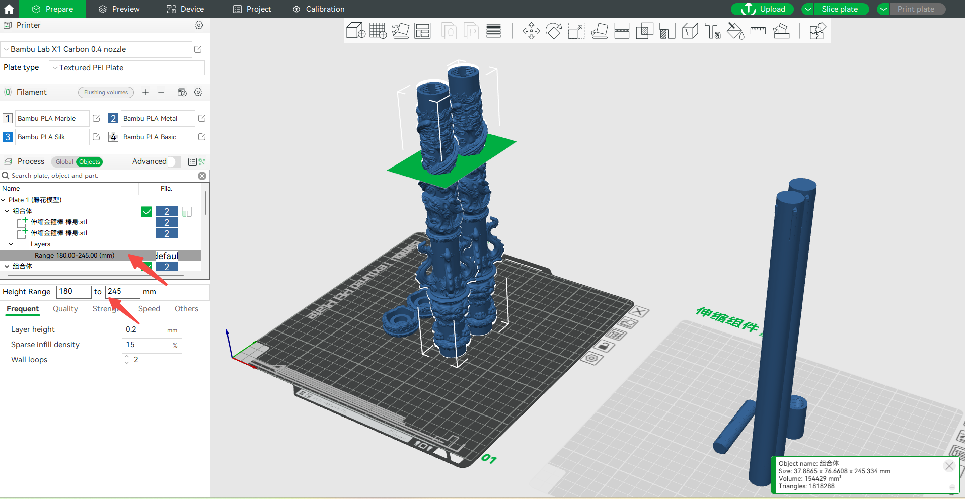
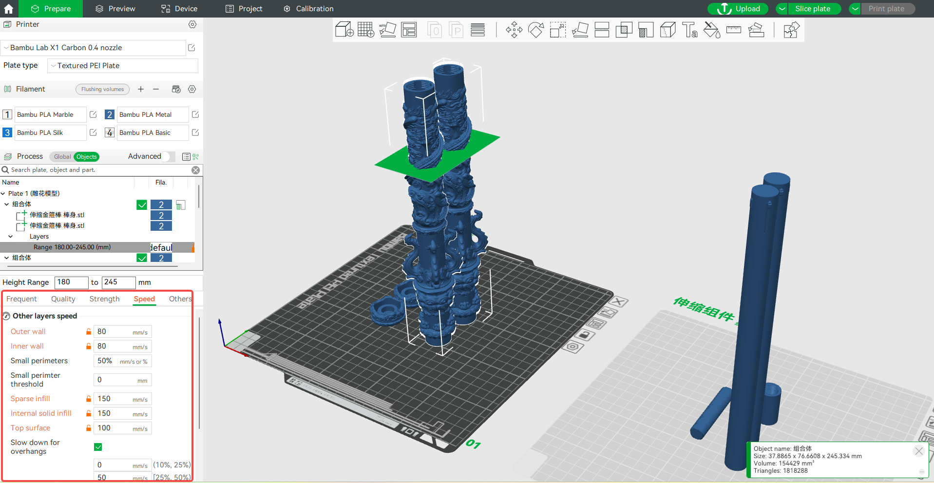
Step 3. Multiple settings can be changed. In this guide, the print speed is adjusted appropriately for the specified height range of the model.
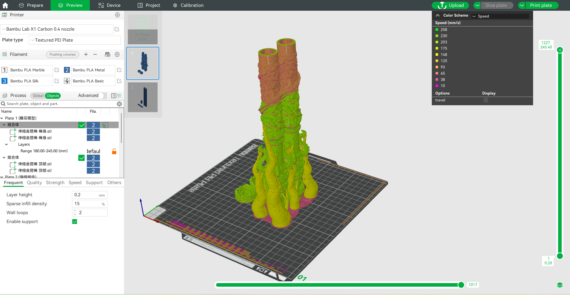
Step 4. Click Slice plate in the upper right corner of the screen. When slicing is complete, select Speed in the Color Scheme to see the difference in speed between the print speed for the specified height range and the rest of the section.

¶ Common Functions of the Modifier
¶ Modify the infill density of the overlap
¶ Add a Modifier
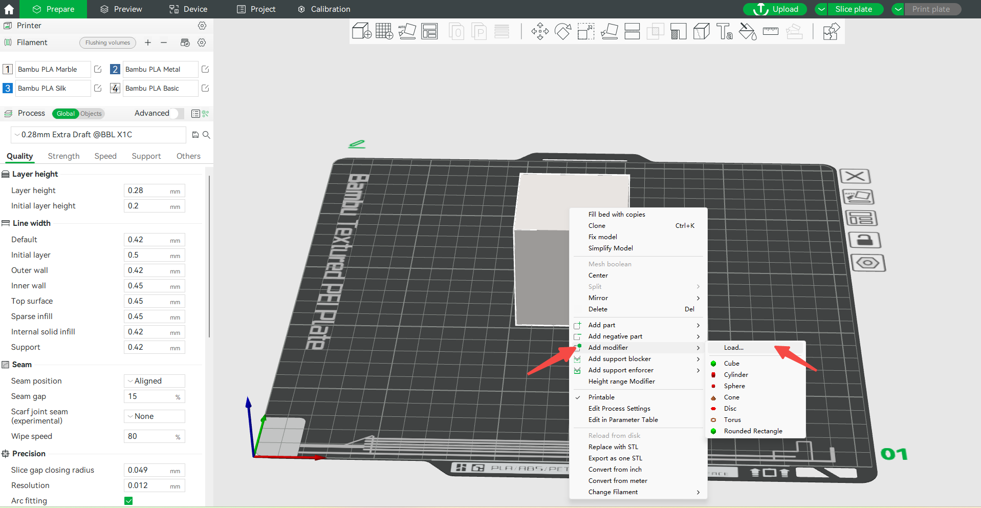
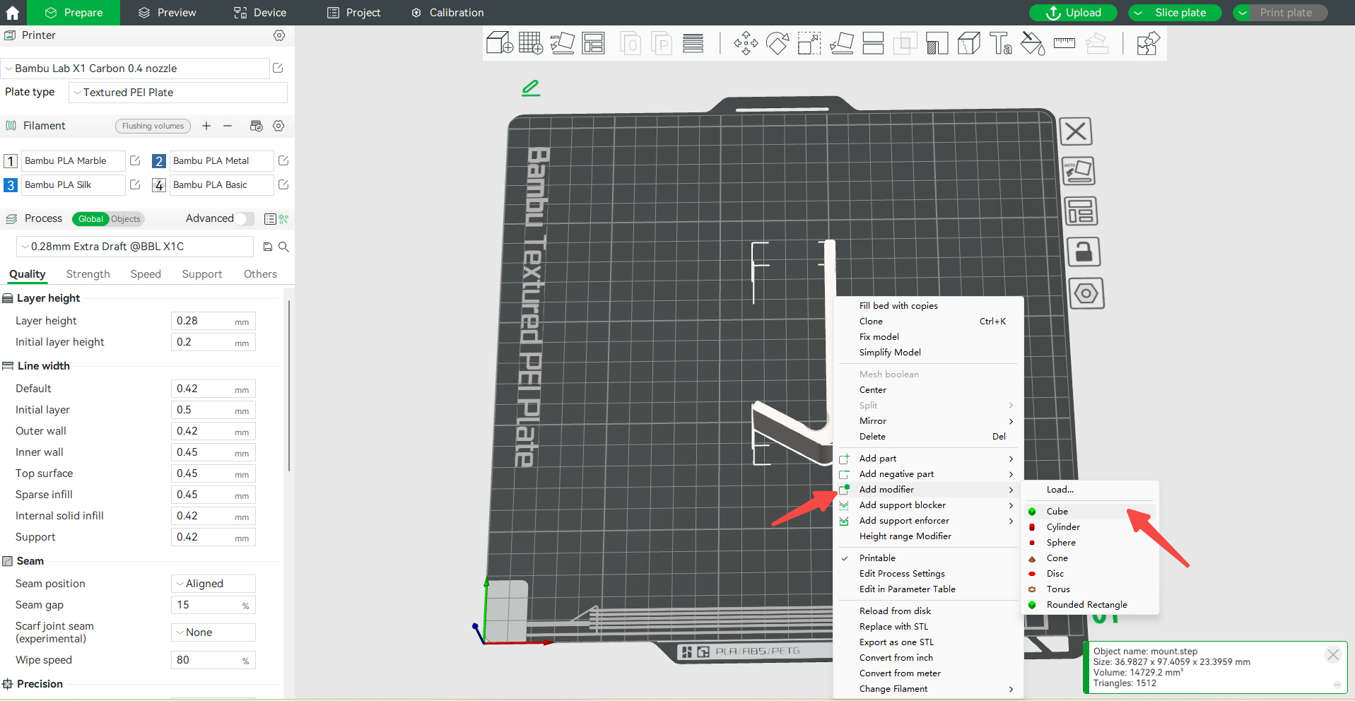
Step 1. Right-click the model on the print plate and click Add modifier in the menu bar to select the type of modifier you want to add.
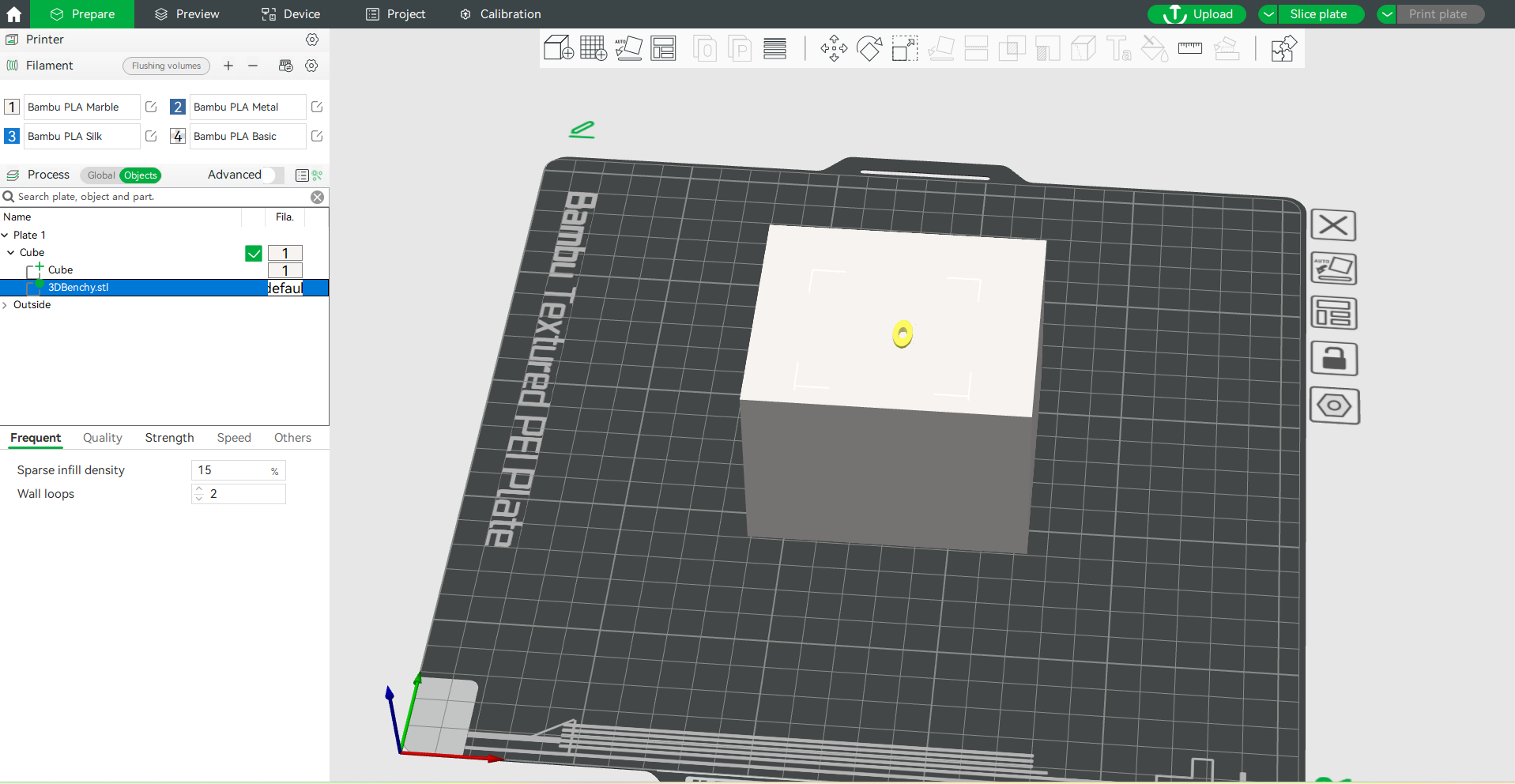
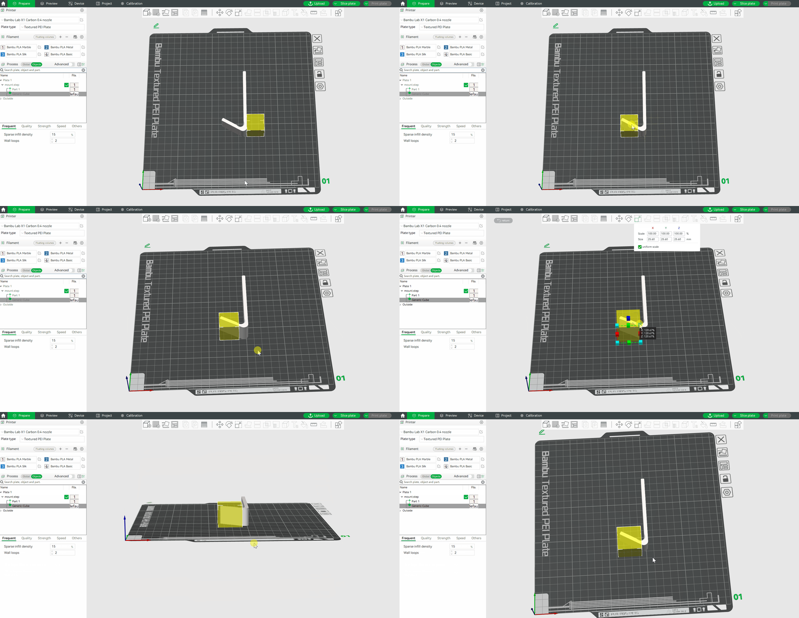
Step 2. Once added, click on the print plate and drag the mouse to get an all-around view of the modifier and adjust the portion of it that overlaps the model.
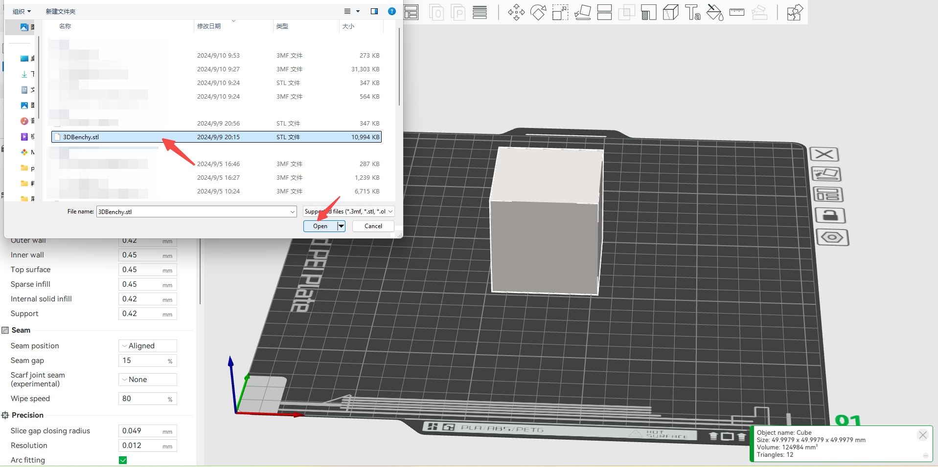
Note: Any .stl model file can be used as a modifier.
- Click Load... in Add modifier to set the stored model file as a modifier.
- Slicing is performed when the modifier is moved to the desired position.
¶ Modify sparse infill density
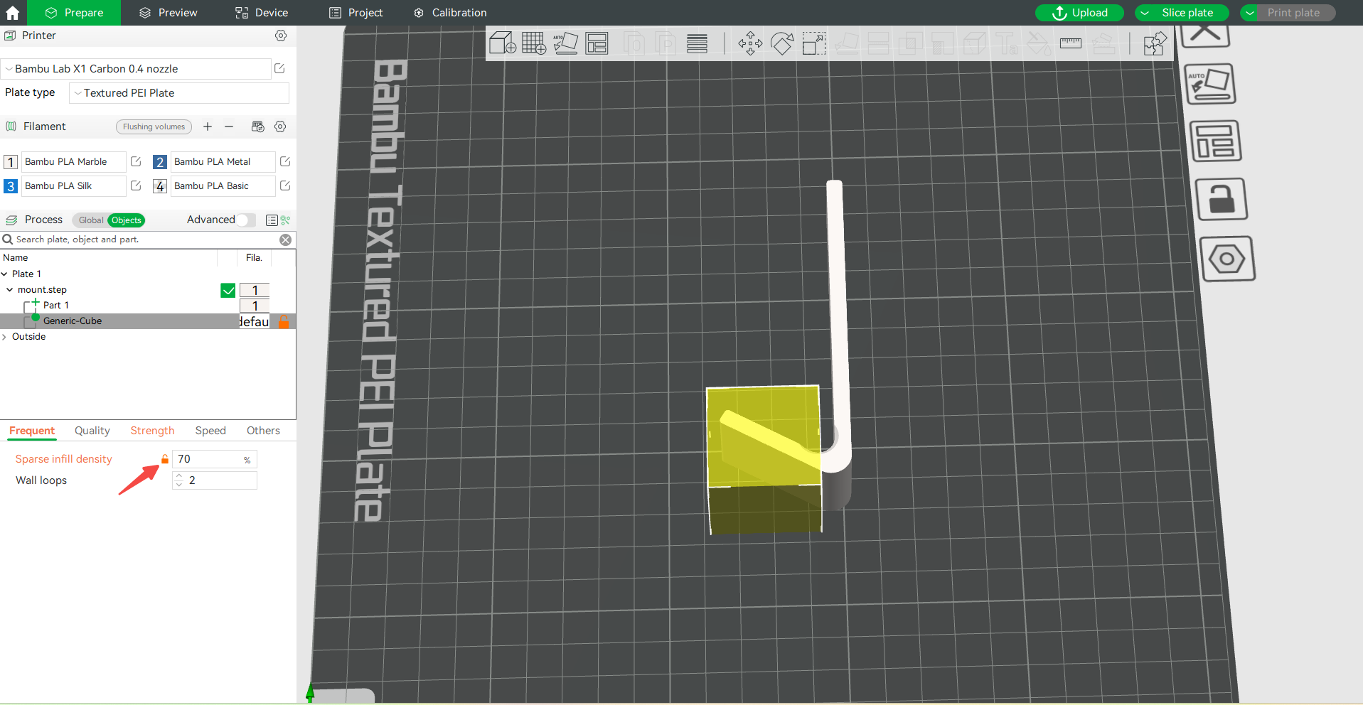
After selecting the modifier, in the Sparse infill density box under the Frequent menu bar on the left side of the screen, enter the desired model fill density value, and press the Enter key to take effect.
¶ Slice plate
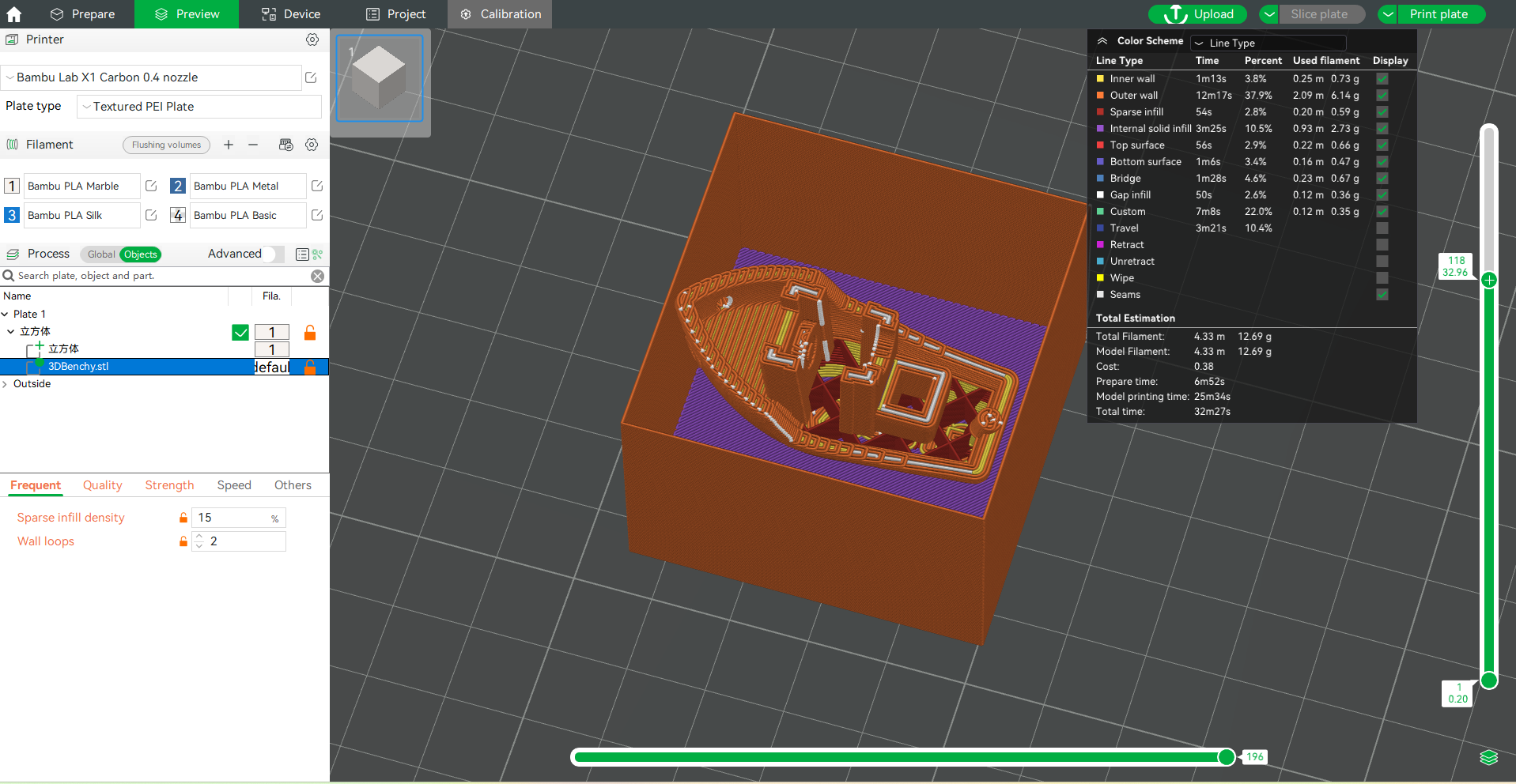
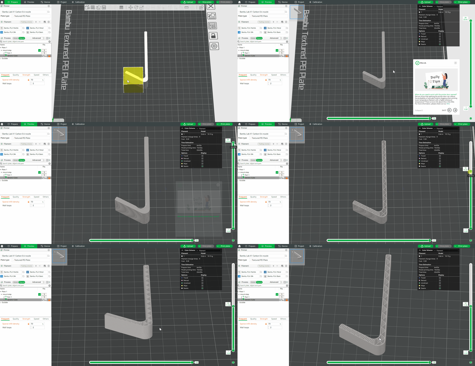
Click on the top right corner of the screen Slice plate. After slicing is complete, move the right progress bar to observe that the infill density of the modifier-covered portion is significantly higher than the rest of the portion.
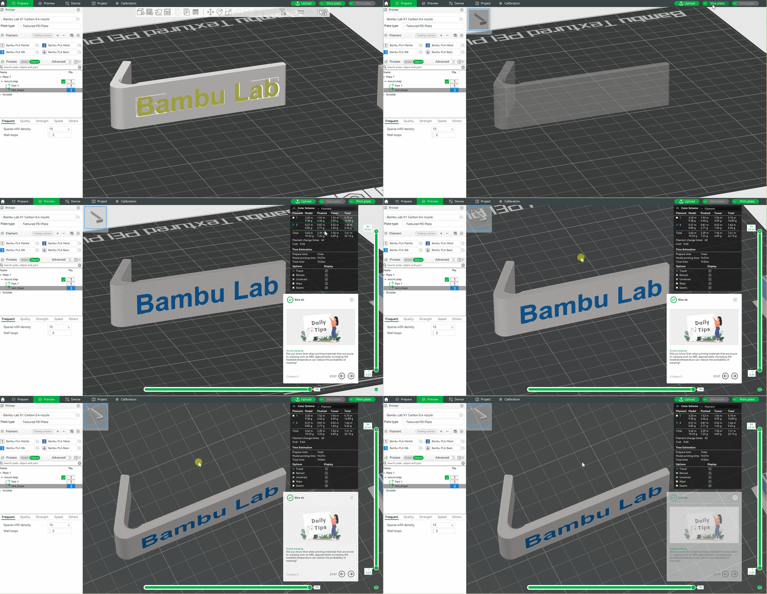
¶ Add text to the surface of model
¶ Add text shape
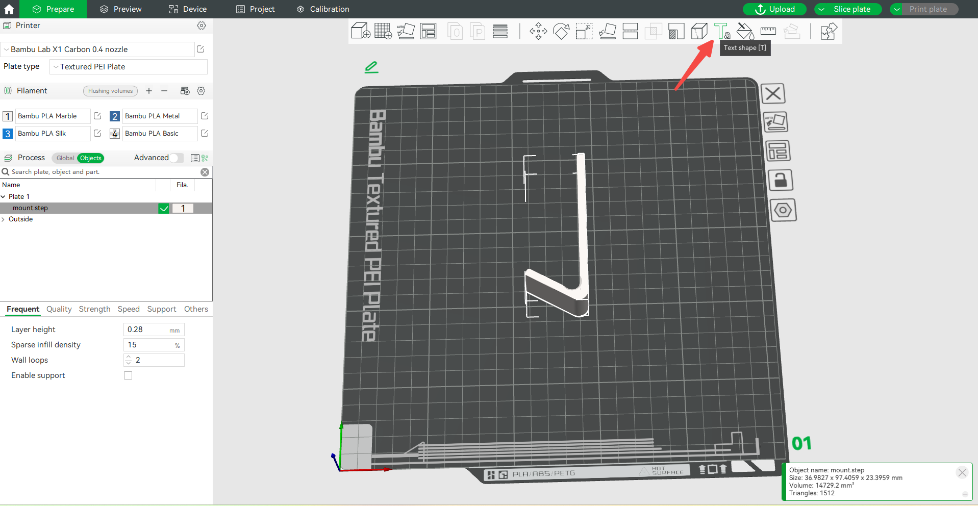
Step 1. Click on the Text shape icon.
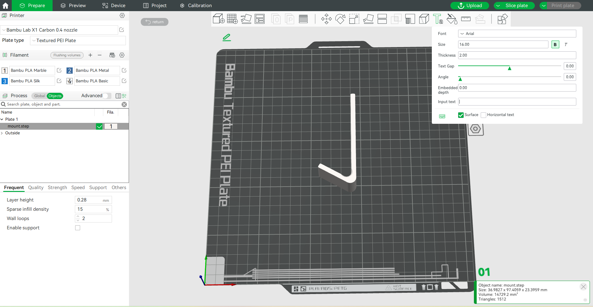
Step 2. Enter text in the Input text box. The text font, size, thickness, etc. can be set.
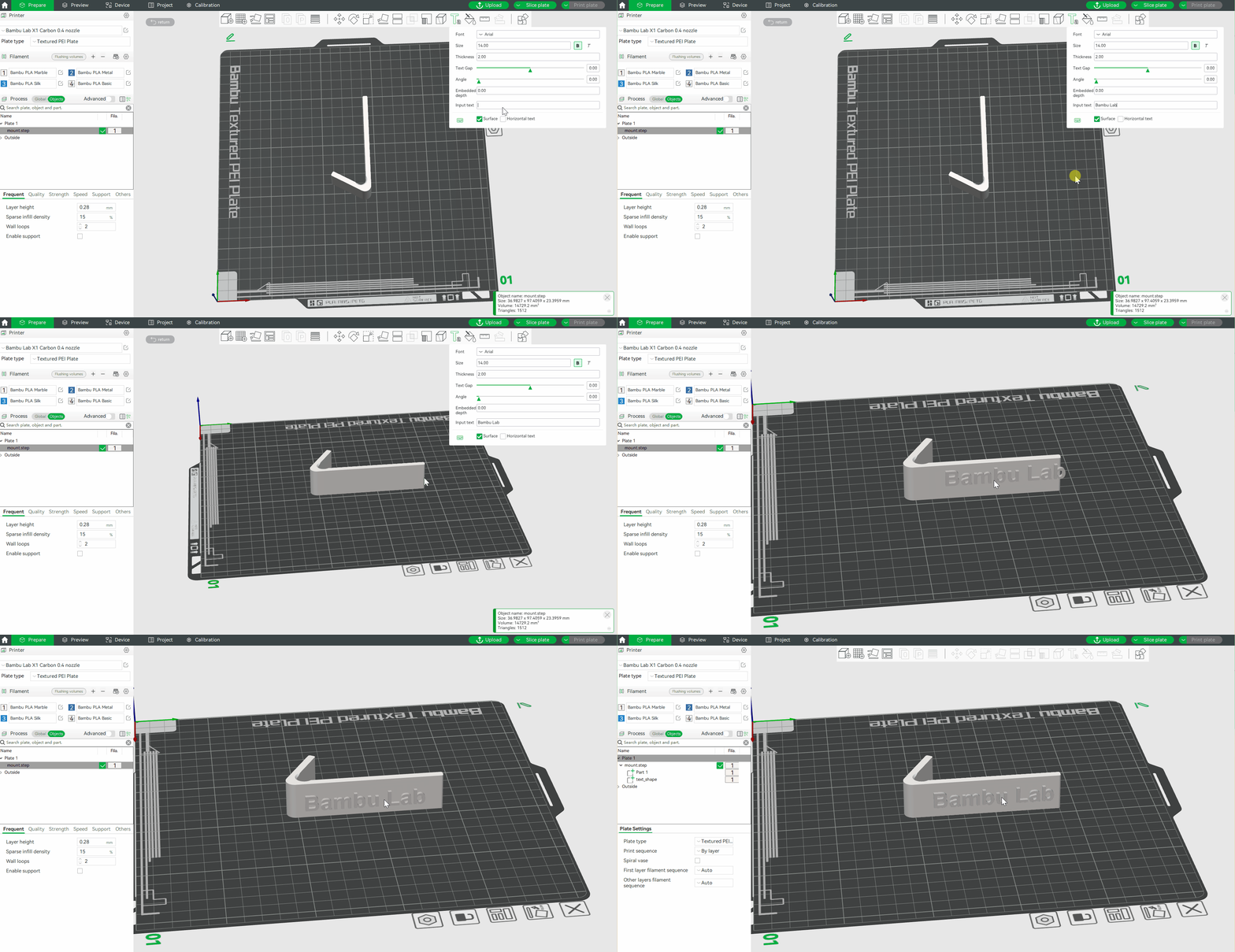
Step 3. Drag the text and drop it anywhere on the model.
¶ Modify the text color
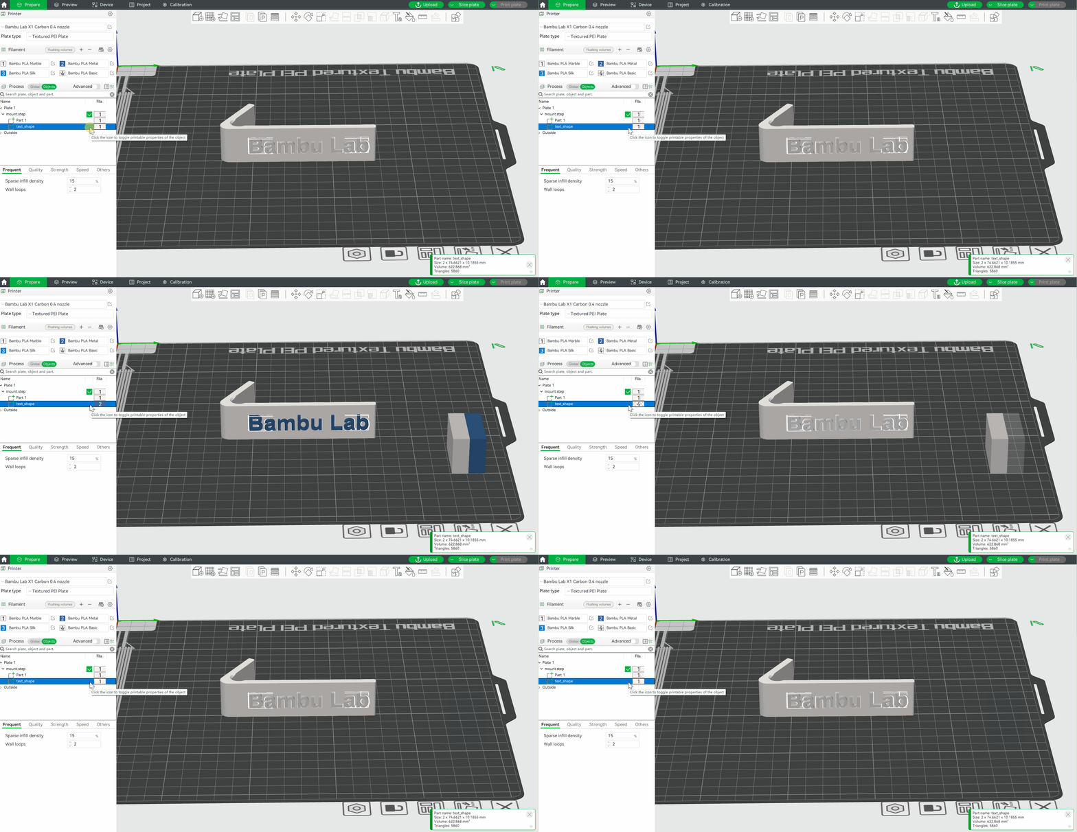
Step 1. Click on the Objects and then click on the text_shape.
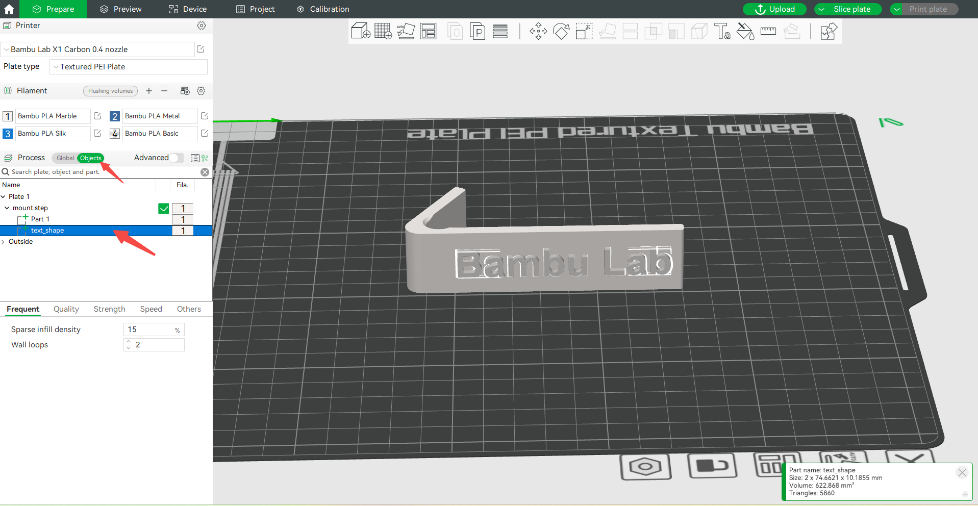
Step 2. Set the desired text color by pressing the filament color number on your keyboard.
¶ Attach text to the surface of the model
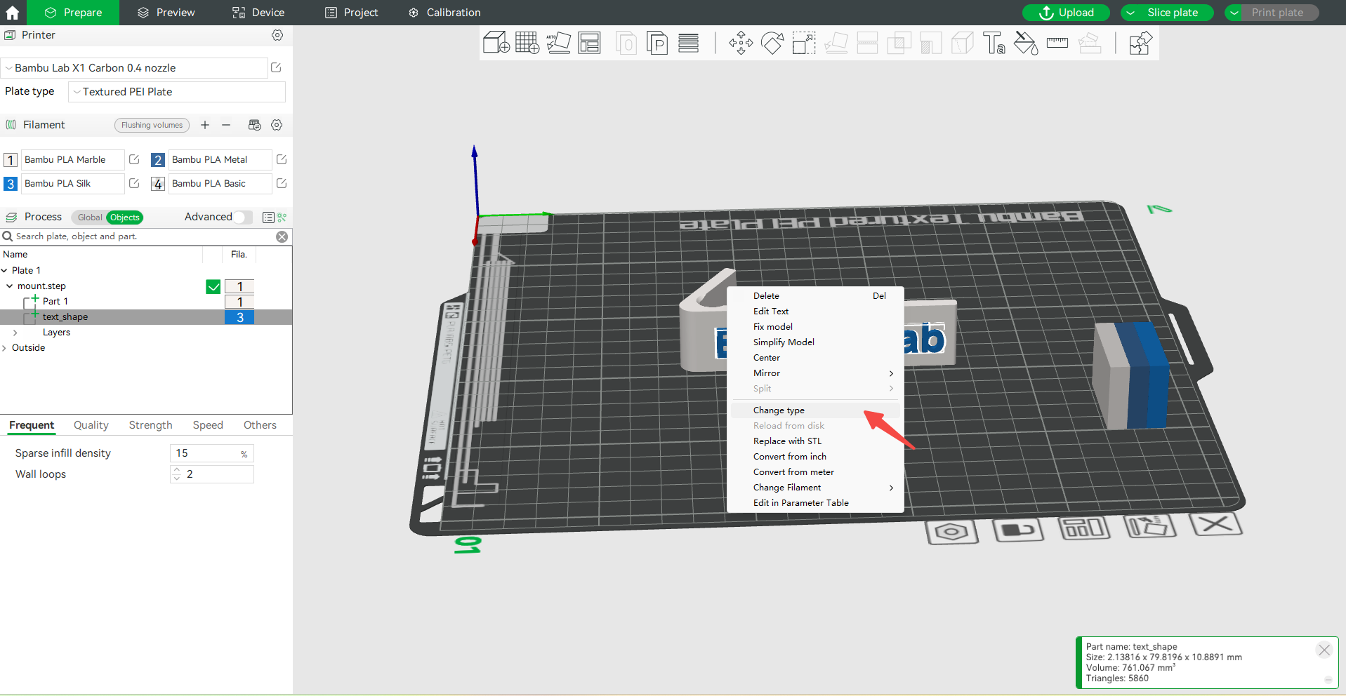
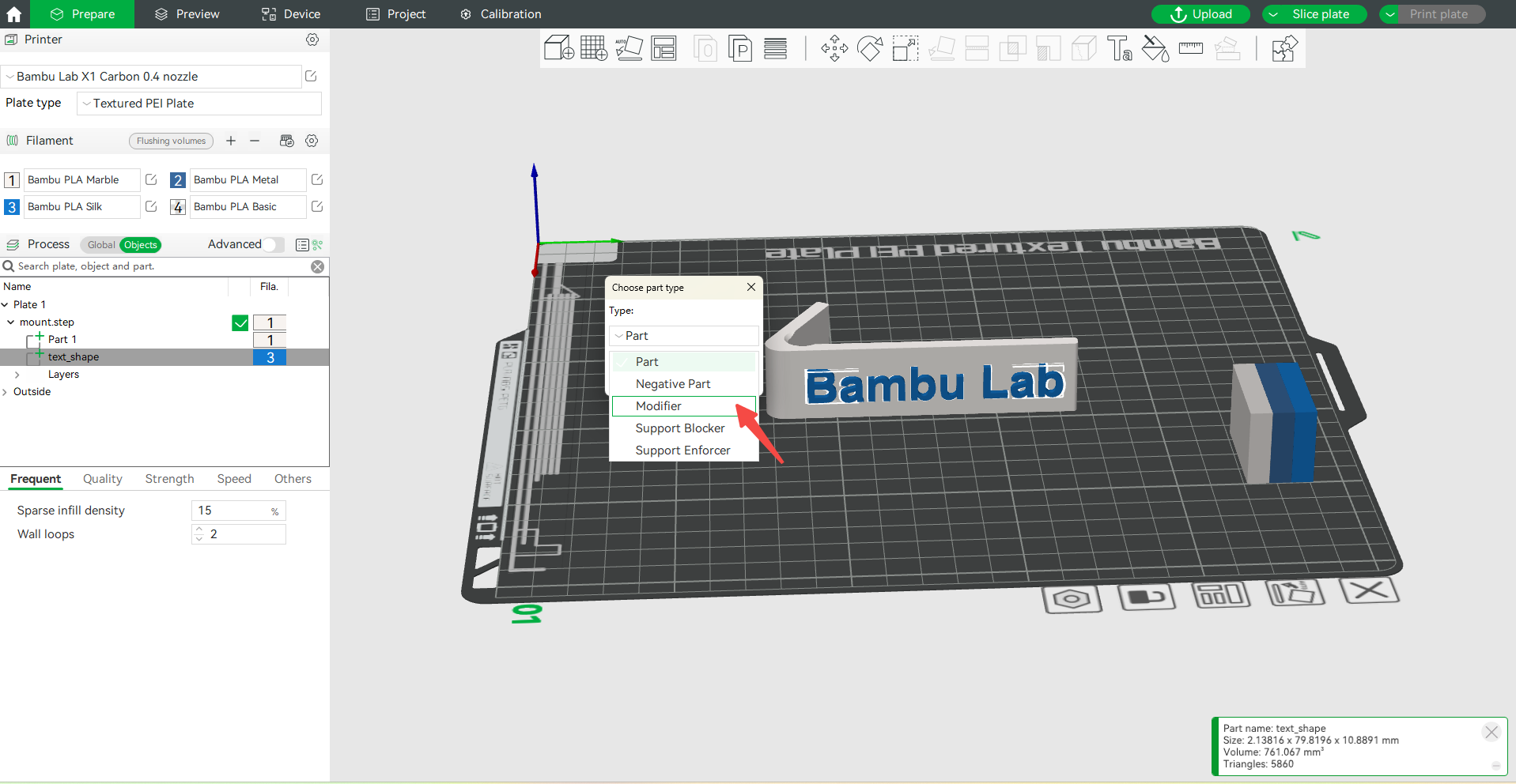
Step 1. Right-click the text and select Change Ttype > Modifier.
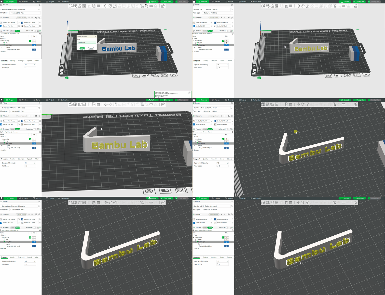
Step 2. Adjust the text position to ensure that the text overlaps the surface of the model.
¶ Slice plate
Click Slice plate in the upper right corner of the screen. When the slice is complete, you can see that the text has been attached to the surface of the model.
¶ End Notes
We hope the detailed guide provided has been helpful and informative.
To ensure a safe and effective execution, if you have any concerns or questions about the process described in this article, we recommend submitting a Technical ticket regarding your issue. Please include a picture or video illustrating the problem, as well as any additional information related to your inquiry.
