¶ XY motor
¶ Tools
H2.0/H1.5 hex key
(Extended and magnetized H2.0 hex key)
Tweezers
¶ Preparation
Disconnect the power cord cable
¶ Disassembly
¶ Step 1 - Remove the excess chute
Remove the rear panel and excess chute by referring to the related content on the Excess chute.
¶ Step 2 - Loosen XY tensioners
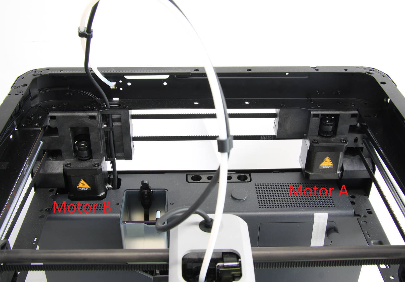
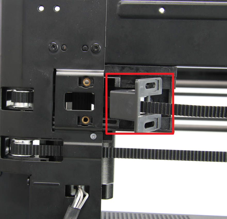
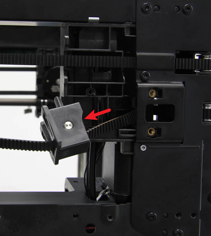
To replace a motor, first determine which motor needs to be replaced. Then, refer to the instructions here XY tensioner idler. This will allow you to access the motor and replace it as needed
 |
 |
¶ Step 3 - Remove motor A
Remove motor A according to the following steps:
¶ 3-1 Disconnect the motor cable
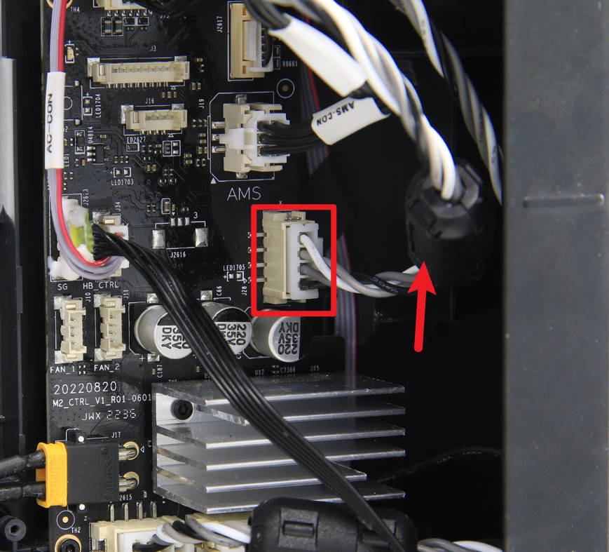
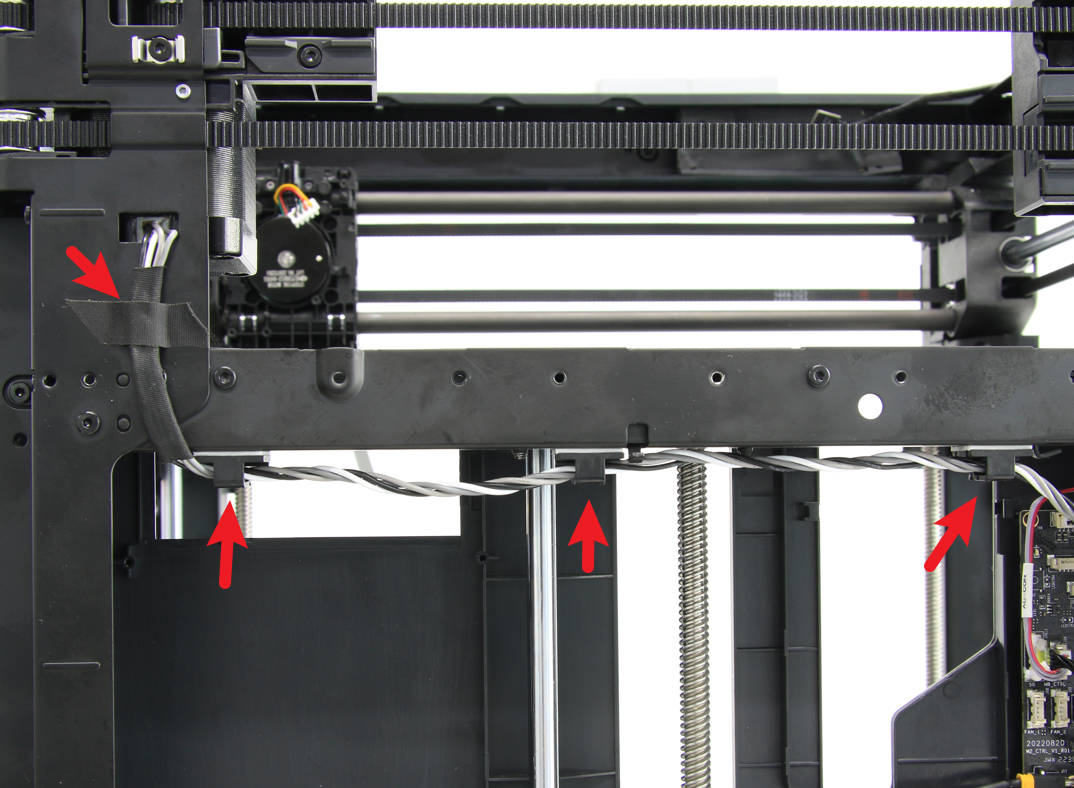
To remove motor A, first disconnect it from the rest of the system. Then, remove the cylindrical ferrite ring from the motor. After the ferrite ring is removed, release the motor cable from any buckles or tapes that are holding it in place.
 |
 |
¶ 3-2 Loosen the belt
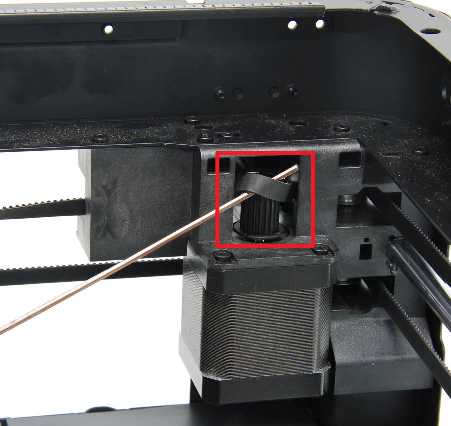
To loosen the belt from the A motor A drive pulley, use a hex key or tweezers to gently lift and pry it off the pulley as shown in the image below.
¶ 3-3 Remove the motor A screws
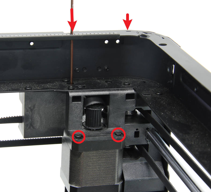
To remove motor A, you will need to locate and remove the four screws that hold it in place. Two of the screws are visible, but the other two will require a long hex key to reach them from the top.
Note: It is important to use a fully magnetized hex key when removing the screws that hold motor A in place. These screws may be tightened quite firmly, so care should be taken to prevent damage to the nuts. Use caution and apply gentle but firm pressure when loosening the screws to ensure that they do not strip or break.
¶ 3-4 Remove motor A
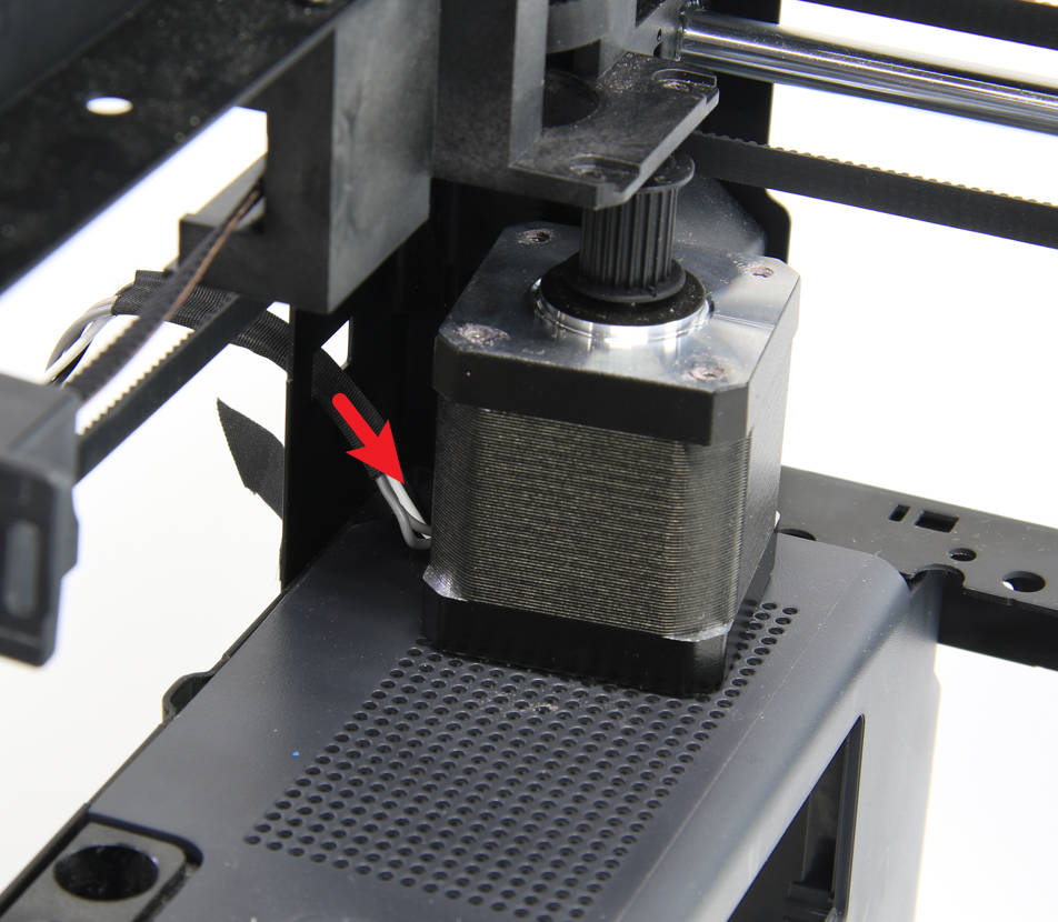
To remove motor A, first, loosen and remove the motor cable. Once the cable is removed, you should be able to lift motor A out of its mount. Take care to support the motor as you remove it to prevent damage.
¶ Step 4 - Remove motor B
Remove motor B according to the following steps:
¶ 4-1 Disconnect the cables
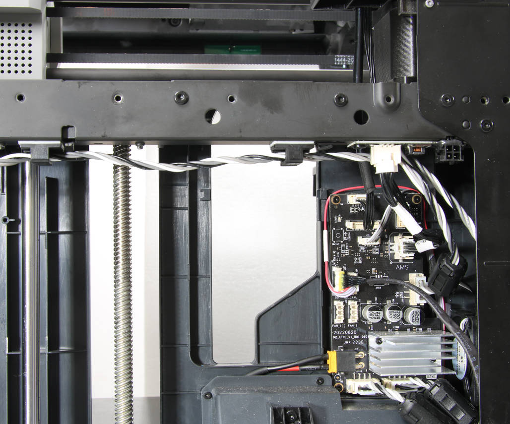
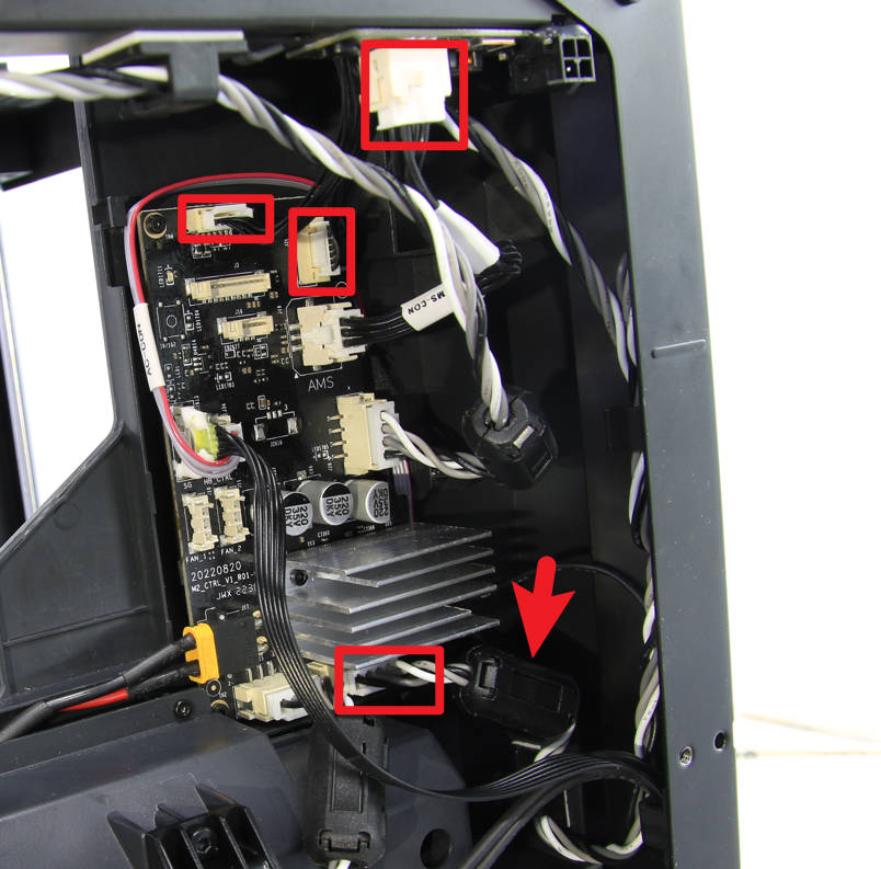
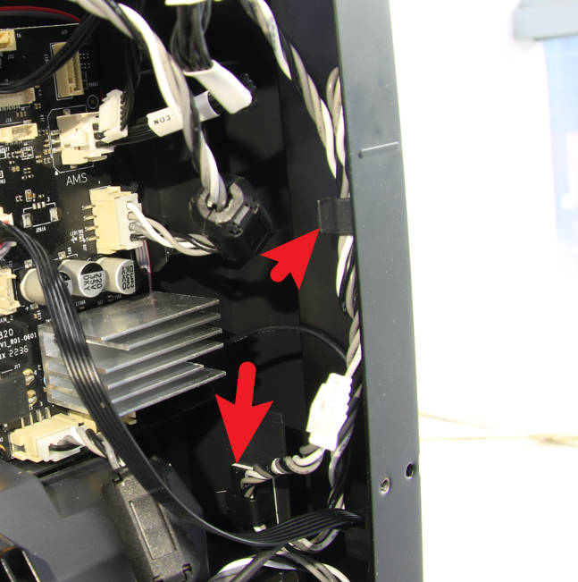
To access the MC board, you will need to disconnect the following cables: the MC-AMS interface cable from the AMS interface board, the MC-AP and MC-TH cables from the MC board, and the motor B cable. Once these cables are disconnected, you can remove the cylindrical ferrite ring from the motor and release the motor cable from any buckles/clips that are holding it in place.
 |
 |
¶ 4-2 Lower the heat bed
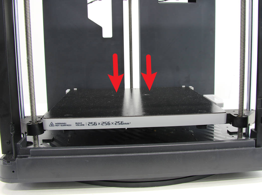
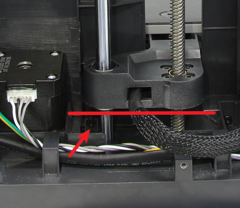
Proceed to tilt the printer and pull on the Z-axis belt to manually lower the heat bed as far as possible without interfering with the removal of the inner sheld screws.
 |
 |
¶ 4-3 Loosen the power socket
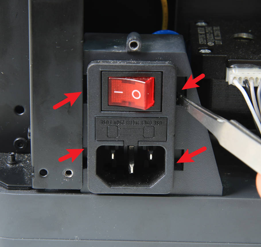
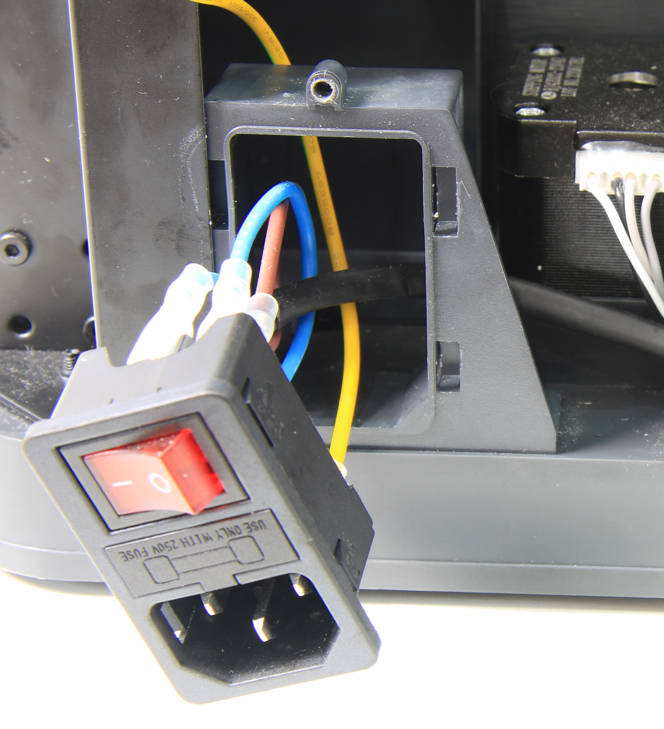
To remove the power socket, use tweezers to gently pry it loose from its mount. Once the socket is loose, you should be able to lift it out of the printer.
 |
 |
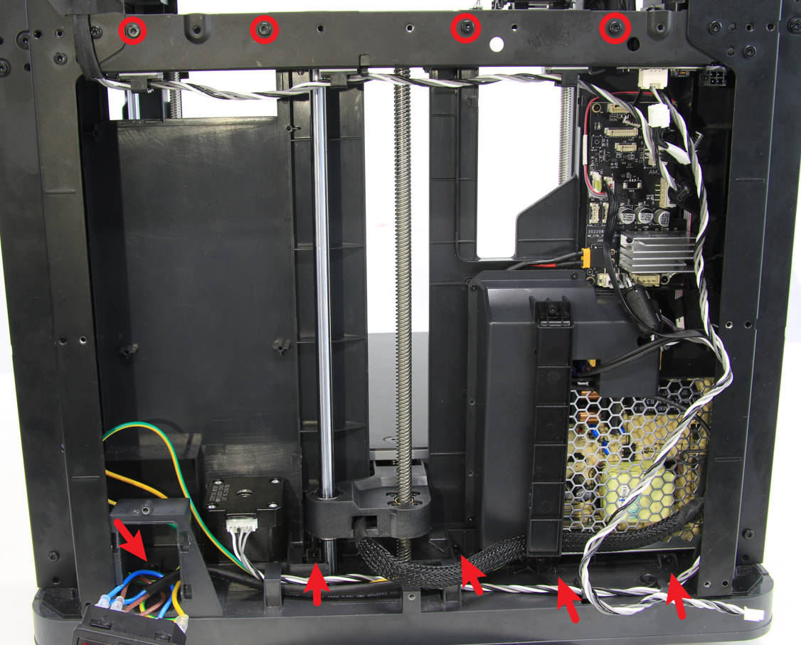
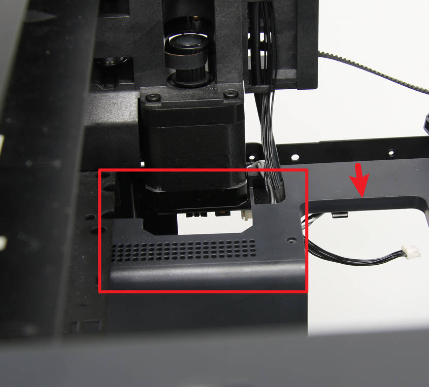
¶ 4-4 Loose the inner sheld
You will need to locate and unlock the nine screws that hold the inner sheld in place. Once the screws are loosened, you can gently lift the inner sheld to create some space at the top. This will allow you to access motor B and remove it as needed.
 |
 |
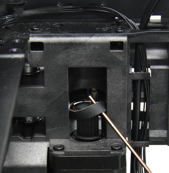
¶ 4-5 Loosen the belt
To remove motor B, you will need to loosen the belt from the motor B drive pulley. Use a hex key or tweezers to gently lift and pry the belt off the pulley. This will allow you to access the motor and remove it as needed. Ensure not to damage the belt or the pulley.
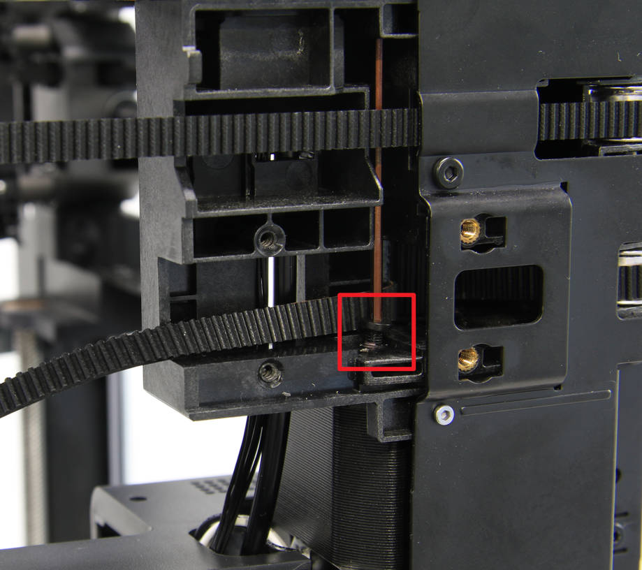
¶ 4-6 Remove the motor B screws
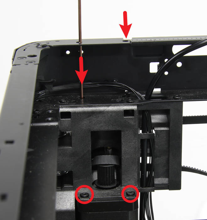
To remove motor B, you will need to locate and remove the four screws that hold it in place. Two of the screws are clearly visible, but the other two will require a long hex key to reach them from the top.
Note: When removing motor B, it is important to use a fully magnetized hex key to prevent slipping or slipping. The screws that hold the motor in place may be tightened quite firmly, so take care to apply gentle but firm pressure and prevent damage to the nuts as you loosen them. Use caution to ensure that the screws do not strip or break as you remove them.
 |
 |
For P1S, 2 screws are blocked by the cable chain cover. You need to remove the cover first:
1. See this article to remove the back cover of the printer.
2. Remove the screw fixing the cable chain cover.
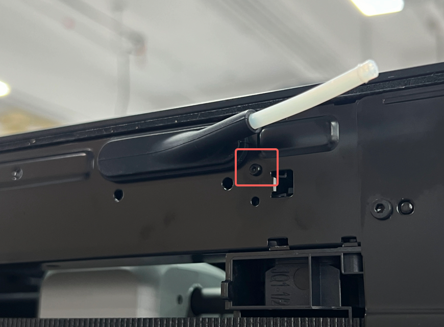
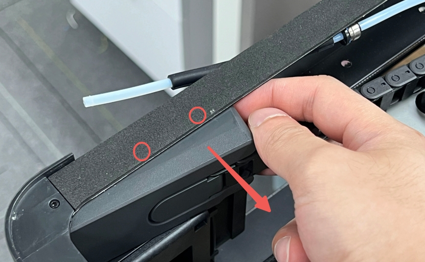
3. Remove the cable chain cover.
The locations marked in red circles are holes for you to insert the wrench to easily access the screws fixing the motor. You can choose to remove the black foam here, or poke through the black foam to expose the holes.
¶ 4-7 Remove the motor B
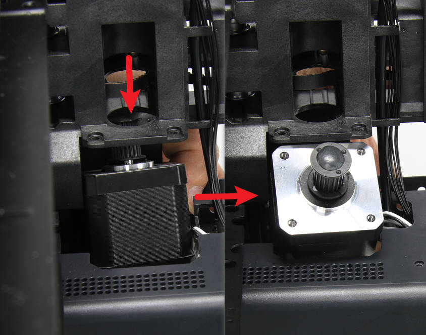
To remove motor B, first gently lower it down into its mount fully as shown in the image below. Then, carefully lift the motor at an angle to free it from its mount. As you lift the motor, be sure to simultaneously pull the motor cable gently out of the cable hole to ensure that it does not get caught/stuck.
¶ Assembly
¶ Step 1 - Install motor A
Refer to the following steps to install the motor A
¶ 1-1 Install the motor A
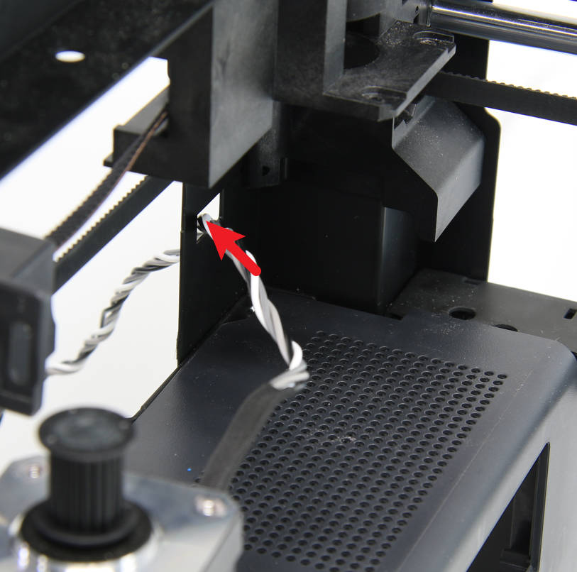
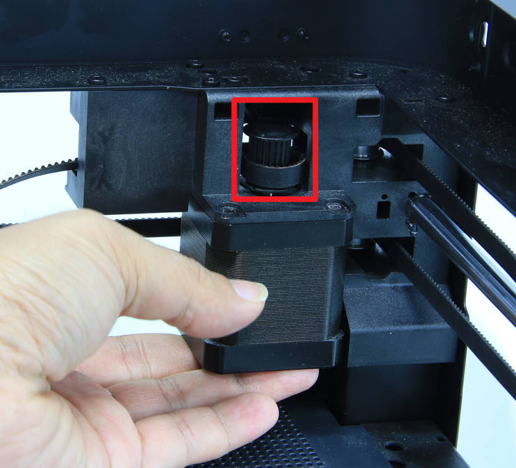
To install motor A, first, pass the motor cable through the cable hole and position the motor on the motor bracket. Then, use a hex key or tweezers to install the belt on the driving pulley. Make sure that the belt is properly seated on the pulley and that it is tightened to the appropriate tension. This will help to ensure that the motor operates smoothly and efficiently.
 |
 |
¶ 1-2 Lock motor A screws
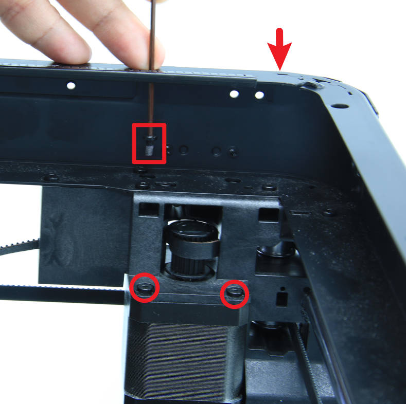
To secure motor A in place, you will need to use a hex key to lock in the four screws that hold it to the motor bracket. Two of the screws can be accessed easily, but the other two will require a long hex key to reach them from the top of the upper beam. Once all four screws are in place, use a hex key to tighten them to the appropriate torque to ensure that the motor is held securely in place. Be cautious and apply gentle but firm pressure to prevent stripping or breaking the screws.
¶ 1-3 Connecting the motor cable
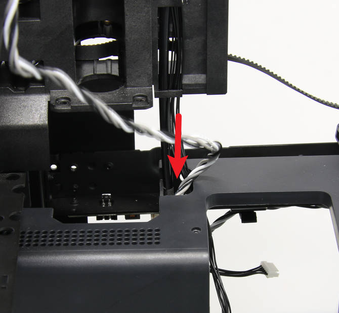
Arrange the motor cable as shown in the image below. Once the cable is properly positioned, install the cylindrical ferrite ring and connect the cable to the connector on the MC board. Ensure the cable is securely seated in the connector and the ferrite ring is properly closed.
 |
 |
¶ Step 2 - Install motor B
Refer to the following steps to install the motor B
¶ 2-1 Install motor B
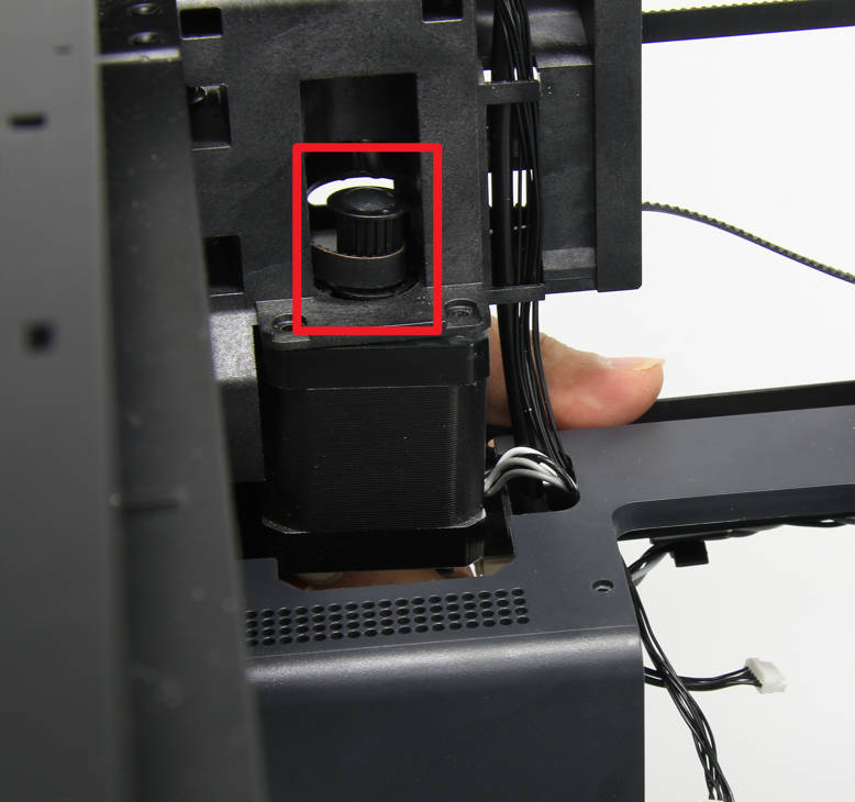
To install motor B, you will need to pass the motor cable through the cable hole and position the motor on the motor bracket. Once the motor is in place, use a hex key or tweezers to install the belt on the driving pulley. Make sure that the belt is properly seated on the pulley and that it is tightened to the appropriate tension to ensure that the motor operates smoothly and efficiently.
 |
 |
¶ 2 -2 Lock motor B screws
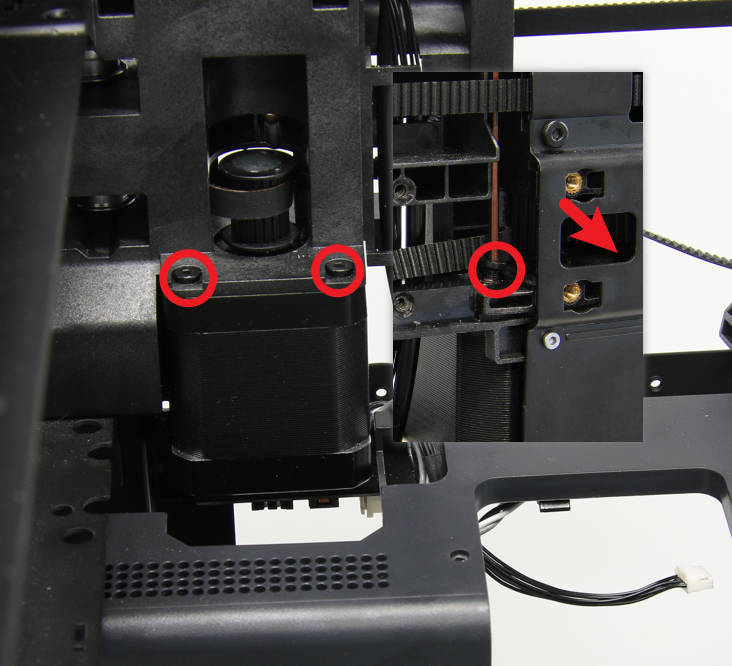
To secure motor B in place, you will need to use a hex key to lock in the four screws that hold it to the motor bracket. The rear screws will require a long hex key from the top of the upper beam. Once all four screws are in place, tighten them to the appropriate torque to ensure that the motor is held securely in place. Be sure to use caution and apply gentle but firm pressure to prevent stripping or breaking the screws.
 |
 |
¶ 2-3 Secure the inner sheld
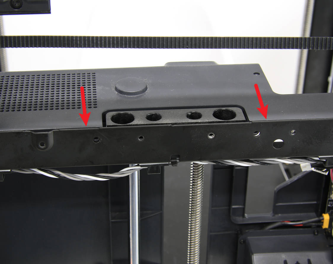
To reinstall the inner sheld, you will need to place it back in position and fit it to the rear beam. Once the inner sheld is properly aligned, use a hex key to lock in the nine screws that hold it in place. Ensure that the screws are tightened to the appropriate torque so that the inner sheld is held securely in place.
 |
 |
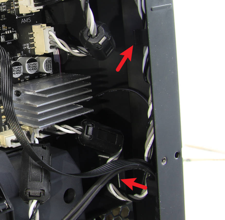
¶ 2-4 Connect cables
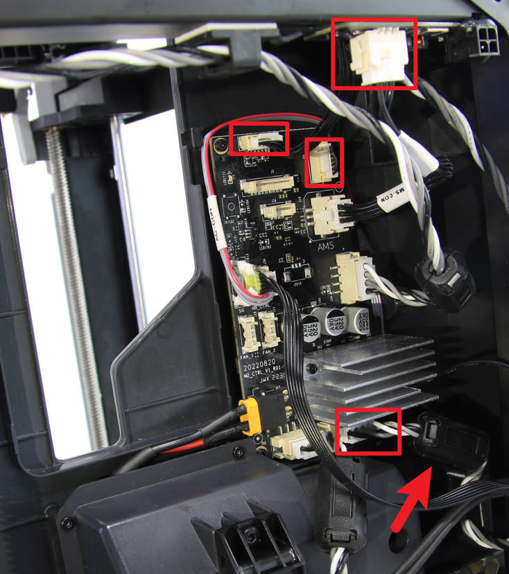
To complete the installation of motor B, you will need to install the cylindrical ferrite ring and connect the motor cable, MC-AP cable, and MC-TH cable to the MC board. Then, connect the AMS interface cable to the AMS interface board and carefully arrange the motor cable to ensure that it is properly positioned.
 |
 |
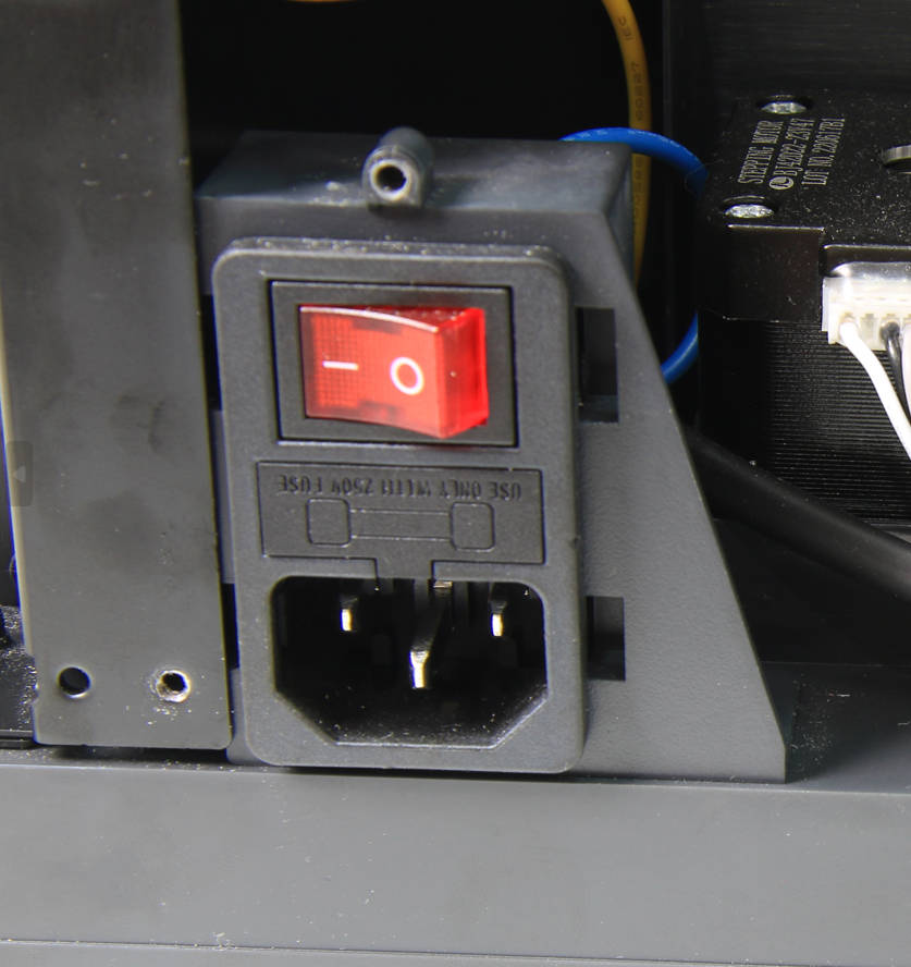
¶ 2-5 Mount the power socket
Mount the power socket back into place.
¶ Step 3 - Install XY tensioners
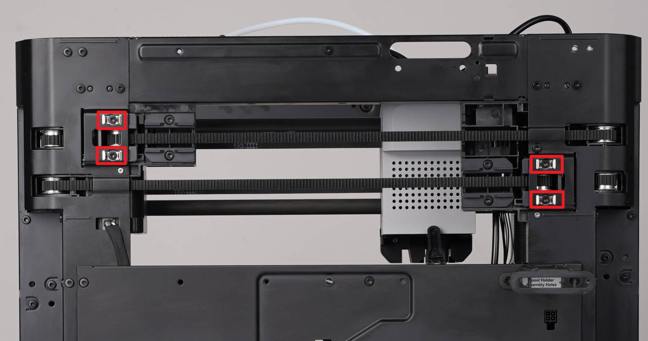
Refer to the relevant content of XY tensioner idler , install the loose tensioner, and re-tension the belt.
¶ Step 4 - Assemble the printer
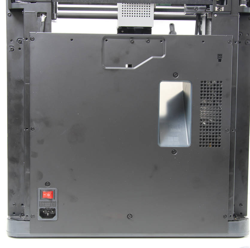
Install the excess chute and the rear panel by referring to the related content on the Excess chute.
¶ How to verify
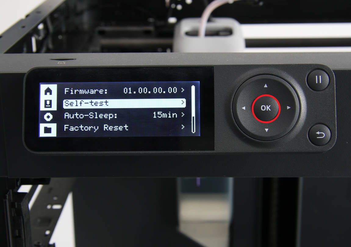
Connect the power cord cable, turn on the printer, and run the device self-test process. If the self-test passes, the operation is successful.
