¶ Phenomenon:
We have identified an issue with the X1 printer: the Heatbed alignment is incorrect, potentially causing interference with the spare chute at the back of the printer. This problem can arise during shipping or if any of the screws are not adequately tightened.
When attempting to home the printer, the backside of the heated bed makes contact with the excess chute, leading to the "Homing Z axis failed [0300 4000]" error.
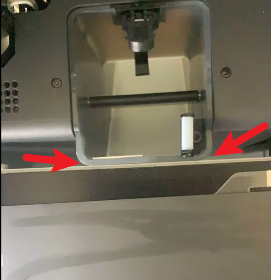
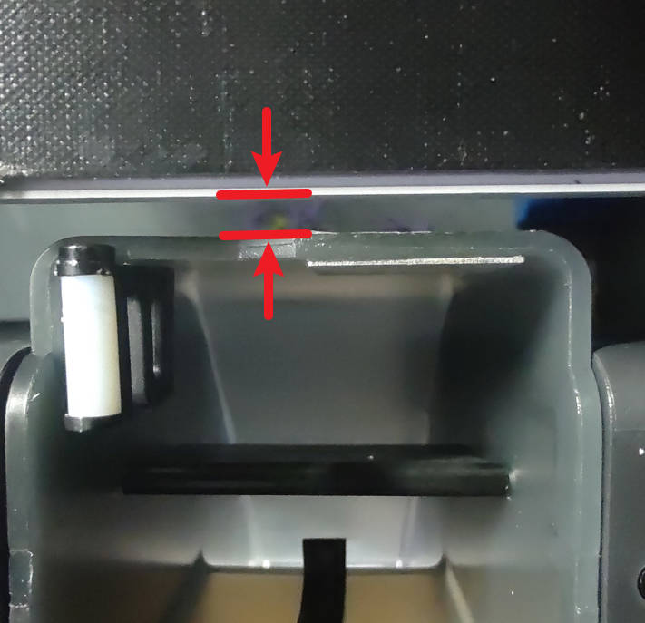
To resolve this issue, it is important to ensure that there is a minimum 2mm gap between the Heatbed and the excess chute. Due to factors such as shipping or loose screws, the Heatbed may have shifted from its original position. Consequently, during the calibration process when the Heatbed moves upward, it comes into contact with the excess chute, becomes stuck, and fails to complete the calibration or homing procedure.
1. The user consistently encounters the "Homing Z axis failed" error.
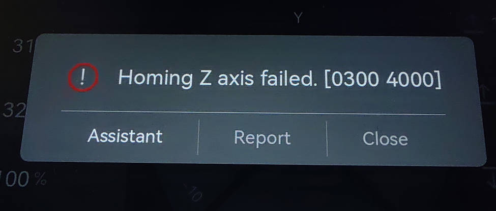
(Note: Please press "Assistant" and follow the guide provided to troubleshoot the issue. The guide can assist you in identifying the cause of the failure.)
2. There is visible interference between the Heatbed and the excess chute.
¶ Solution:
Please reset the position of the Heatbed.
¶ Step 1 - Power OFF the printer
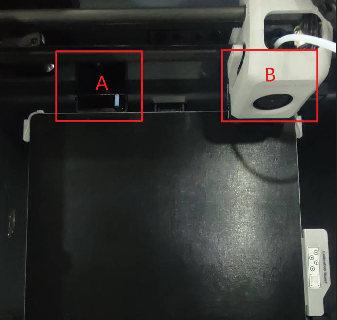
Please power off the printer and manually move the toolhead towards the excess chute (A) or to the right side (B) to prevent accidental contact between the Heatbed and the nozzle.
¶ Step 2 - Loosen screws
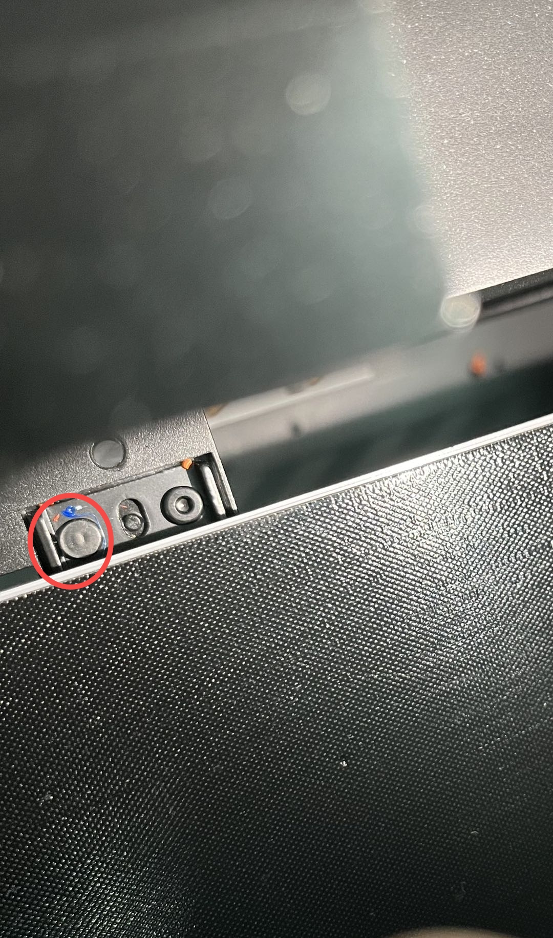
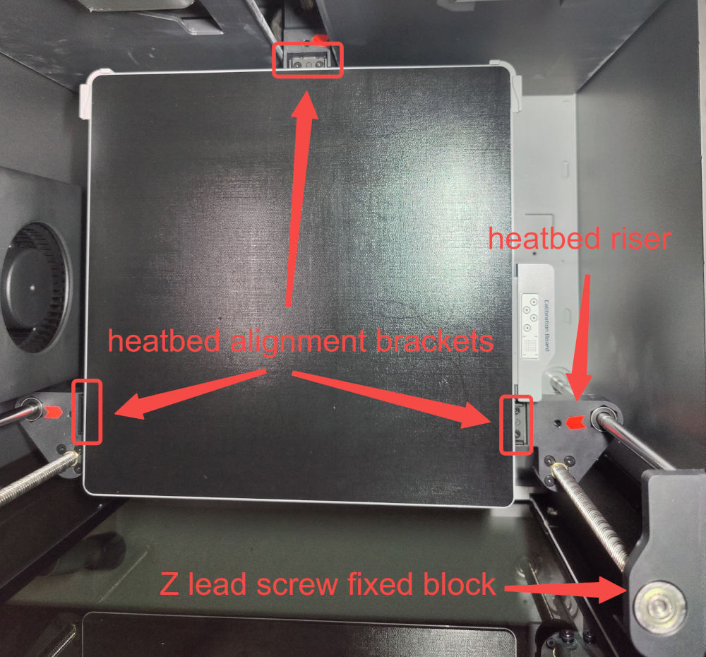
Loosen the 6 screws that secure the 3 Heatbed alignment support brackets. It is not necessary to remove the screws completely, just ensure that they are loosened.
¶ Step 3 - Pull the Heatbed towards the front door
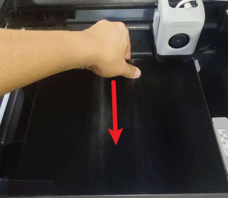
Next, gently pull the Heatbed towards the front, away from the excess chute. Apply only a slight force as it will move only a few millimeters. This action will properly align the bed and increase the gap between the back side of the bed and the excess chute.
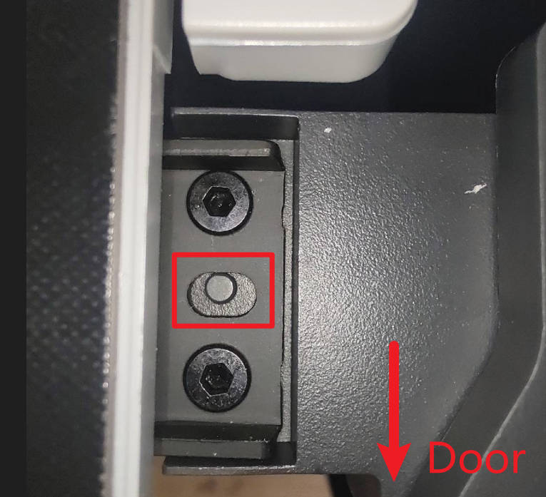
While gently pulling the Heatbed towards the front, please verify that the left and right alignment pins are in contact with the rear edge of the heatbed support bracket alignment oval (refer to the picture).
 |
 |
¶ Step 4 - Re-tighten the screws
While continuing to hold the Heatbed pulled towards the front, carefully examine whether there is a gap between the heatbed and the excess chute, ensuring that they do not make contact. Retighten the 6 screws and verify that the gap is still present and the alignment pins are correctly aligned. If not, repeat the process by loosening the 6 screws and returning to step 3.
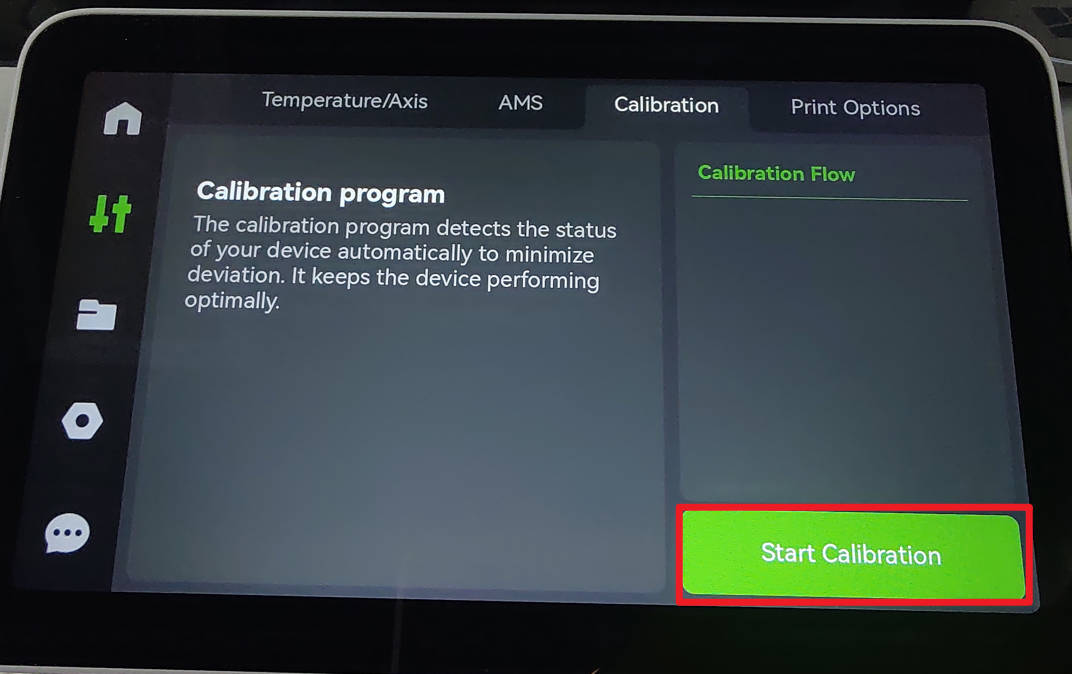
¶ Step 5 - Calibration
Please power on the printer and proceed to run the calibration procedure.
¶ End Notes
We hope the detailed guide provided has been helpful and informative.
To ensure a safe and effective execution, if you have any concerns or questions about the process described in this article, we recommend submitting a Technical ticket regarding your issue. Please include a picture or video illustrating the problem, as well as any additional information related to your inquiry.