¶ AMS Connector Board
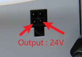
The AMS Connector Board is a circuit board that provides 24V power and also handles communication between the AMS and the printer.
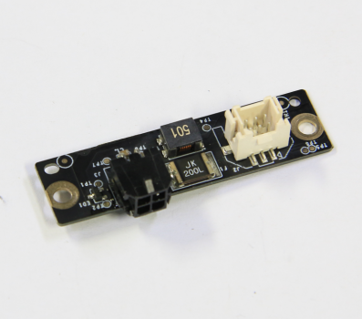
You can purchase it at our store here: AMS Connector Board
¶ When should you replace the AMS Connector Board?
Should there be a power supply or communication failure with the AMS.
¶ Tools and materials needed
- New AMS interface board
- H2.0 Allen key.
¶ Safety warnings and machine state before starting operation
Prior to commencing with the process in this guide, please make sure the machine is switched off. This guide will require you to disconnect all cables from the AMS along with the PTFE and buffer.
¶ Operation guide
¶ Step 1 - (Disassembly) Disconnect the PTFE tube
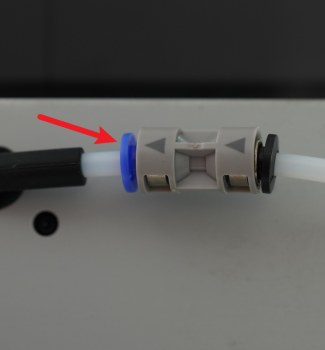
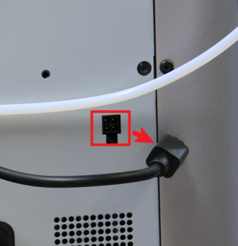
Press on the plastic coupler to disconnect the PTFE tube. Unlock the 4-pin cable and disconnect it from the printer.
 |
 |
¶ Step 2 - Remove the Filament Buffer
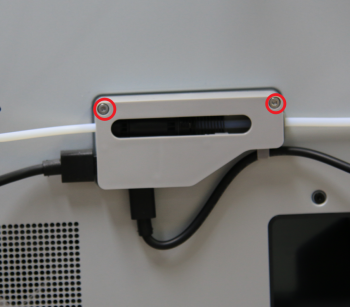
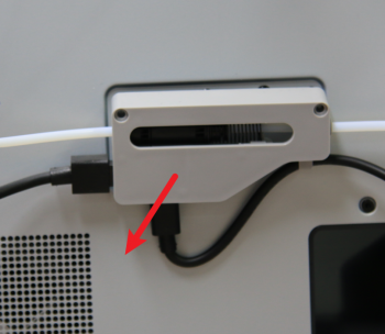
Remove the 2 screws holding the filament buffer to remove it.
 |
 |
¶ Step 3 - Disconnect the power cord
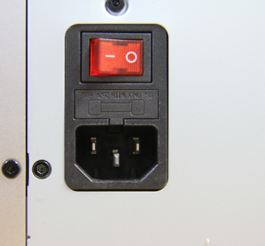
Disconnect the power cord from the power socket.
¶ Step 4 - Remove screws
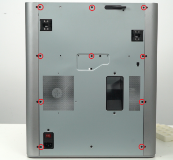
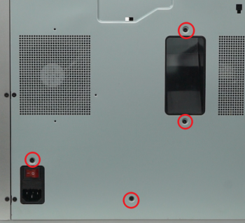
Undo the screws at the back of the printer as marked below. There are a total of 14 screws to undo, 10 of them in the first image and 4 in the second image as shown below.
 |
 |
¶ Step 5 - Remove the rear cover
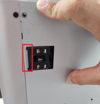
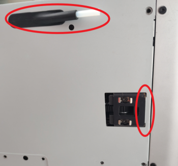
To remove the rear cover, it is important to first pull the left side so that the left belt tension port doesn't get in the way, followed by the right side. Push the PTFE tube outlet inwards to free it from the cover.
 |
 |
¶ Step 6 - Remove the excess chute
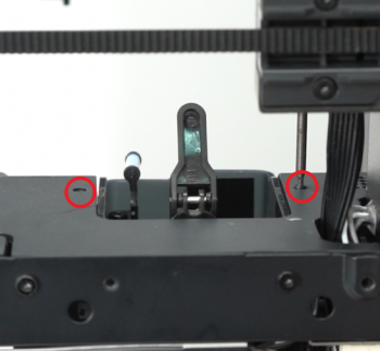
Undo the 2 screws located at each side of the excess chute. once done, take out the excess chute.
 |
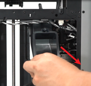 |
¶ Step 7 - Disconnecting the board cable
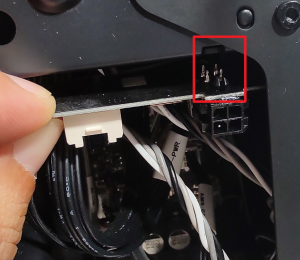
Disconnect the cable shown in the below image from the AMS interface board which is located at the top right-hand side of the back of the printer.
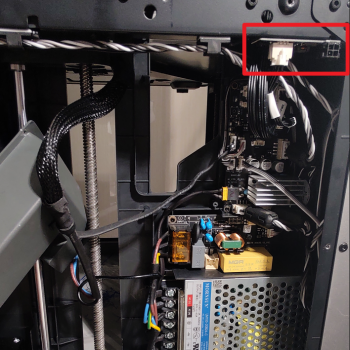 |
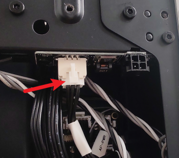 |
¶ Step 8 - Removing the AMS Connector Board
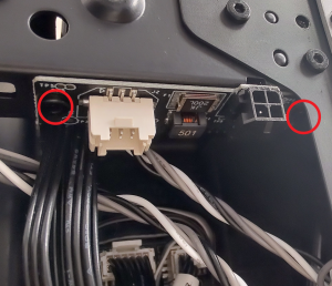
Undo the 2 screws holding the AMS Connector Board, and then remove the board itself.

¶ Step 9 - (Assembly) Installing the AMS Connector Board
To install the AMS Connector Boardd, we will reverse the steps taken so far. First, secure the new interface board back in position with 2 screws.
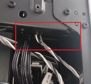 |
 |
 |
¶ Step 10 - Connecting the cable
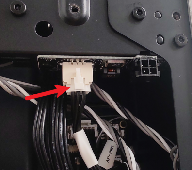
Connect the cable back and secure it to the AMS Connector Board.
¶ Step 11 - Installing the excess chute
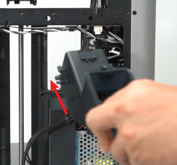
Install the excess chute by sliding it back in its position, pay attention to the protruding tabs on both sides of the chute. Finally, secure it in place with 2 screws at each side of the top of the chute.
 |
.png) |
¶ Step 12 - Installing the rear cover
First, pass through the tube bracket and then secure the right side of the back cover past the right belt tensioner as shown below, followed by the left belt tensioner.
.png) |
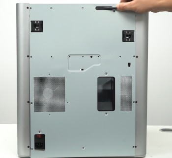 |
¶ Step 13 - Locking screws
Screw the back panel back on. Take note of the different types of screws (10 and 4) used as pointed out previously.
.png) |
.png) |
¶ Step 14 - Installing the AMS buffer
Install the AMS buffer back in place with 2 screws.
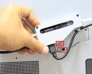 |
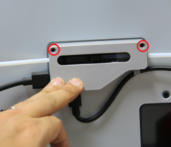 |
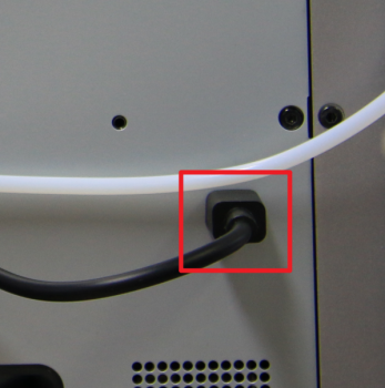
¶ Step 15 - Connecting the tube and cable
Connect the PTFE tube by simply pushing it against the PTFE outlet at the back of the machine, and connect the 4-pin Bambu bus cable.
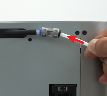 |
 |
¶ How to verify completion/success
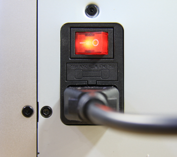
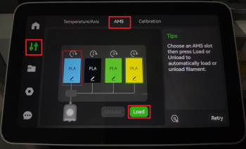
Connect the power cord and turn on the power. On the display screen, press the AMS label on the screen as shown below, it will display the AMS control panel. Press "Load" to run the filament loading process, if the process is completed without any error, the AMS interface board replacement is complete and successful.
 |
 |
Should you come across any issues, first retrace your steps and check all connections to try again. If problems persist, contact the service team for further assistance.