¶ Applicable models of printers
X1E
¶ Power Switch
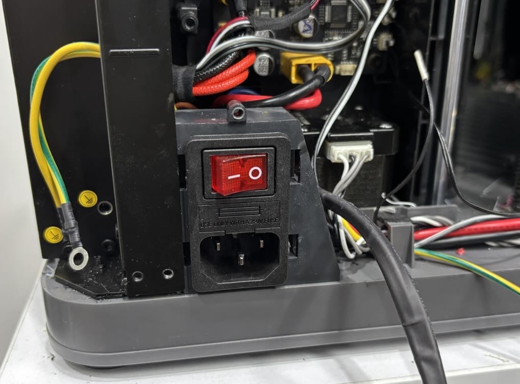
The power switch assembly is a module that mounts to the lower left corner of the back of the printer. It contains a power cord receptacle, a switch that controls power to the printer, and cables for connecting the printer's power supply, AC power strip, and ground.
¶ When to use?
- The switch is damaged
- The connecting cable is damaged
- The power switch assembly has poor contact
¶ Safety Warning
IMPORTANT!
It's crucial to power off the printer before conducting any maintenance work, including work on the printer's electronics and tool head wires. Performing tasks with the printer on can result in a short circuit, leading to electronic damage and safety hazards.
During maintenance or troubleshooting, you may need to disassemble parts, including the hotend. This exposes wires and electrical components that could short circuit if they contact each other, other metal, or electronic components while the printer is still on. This can result in damage to the printer's electronics and additional issues.
Therefore, it's crucial to turn off the printer and disconnect it from the power source before conducting any maintenance. This prevents short circuits or damage to the printer's electronics, ensuring safe and effective maintenance. For any concerns or questions about following this guide, open a new ticket in our Support Page and we will do our best to respond promptly and provide the assistance you need.
¶ Tools and materials needed
- New power switch assembly
- H1.5 Allen key
- H2.0 Allen key
- Phillips screwdriver
- Tweezer, spudger, or other flat tool
¶ Remove the power switch
¶ Step 1: Disconnect the power cable
Turn off the power and unplug the power cable from the power switch assembly.
¶ Step 2: Remove the back panel
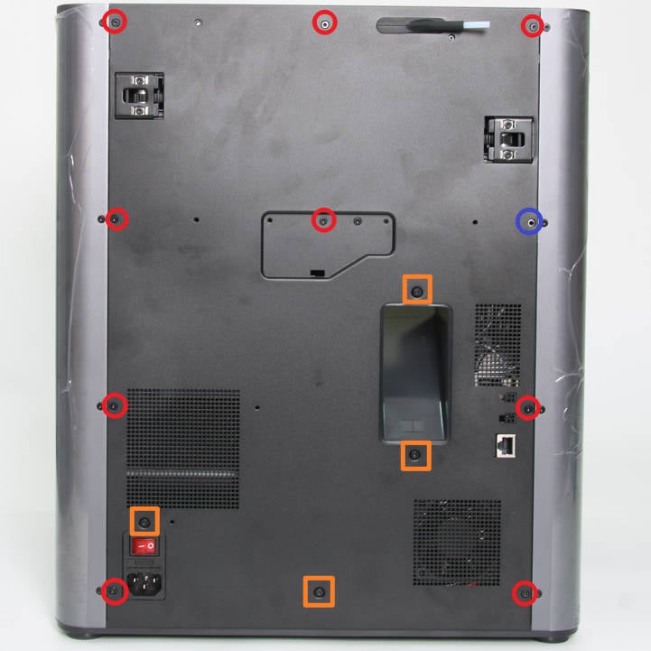
- Remove the glass cover, and then use an H2.0 Allen key to remove 9 screws A (red), 4 screws B (orange), and 1 screw C (purple) as shown in the figure below;
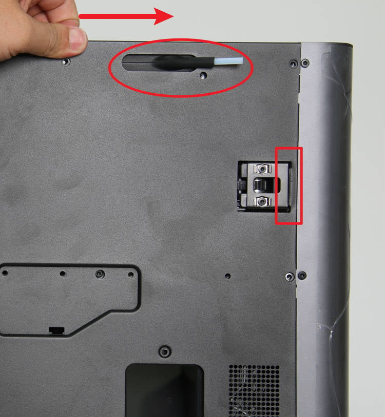
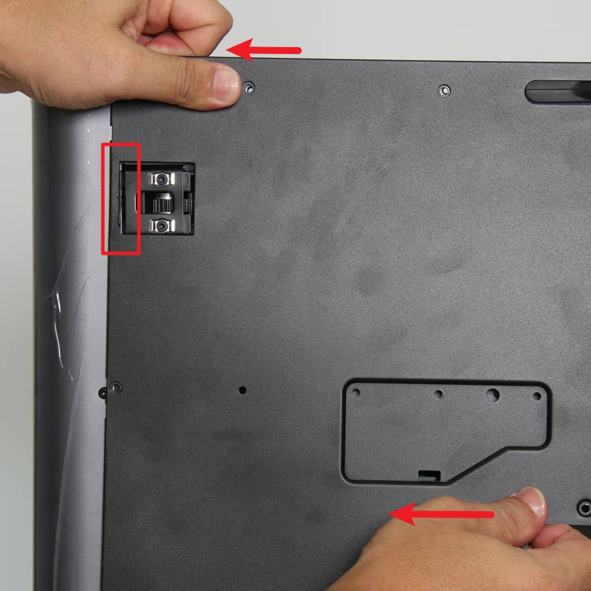
- After removing the screws, first push the back panel slightly to the right to loosen the back panel from the right tensioner; then push to the left to loosen the back panel from the left tensioner and remove the back panel.
 |
 |
¶ Step 3: Remove the purge chute
- First remove 2 screws with an H1.5 Allen key;
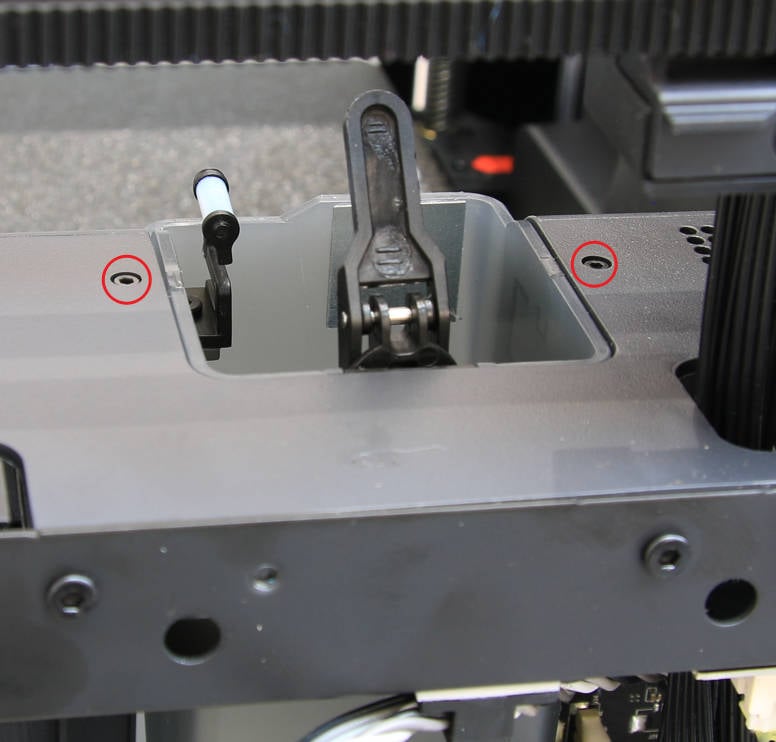
- Then remove 1 screw with an H2.0 Allen key and remove the purge chute.
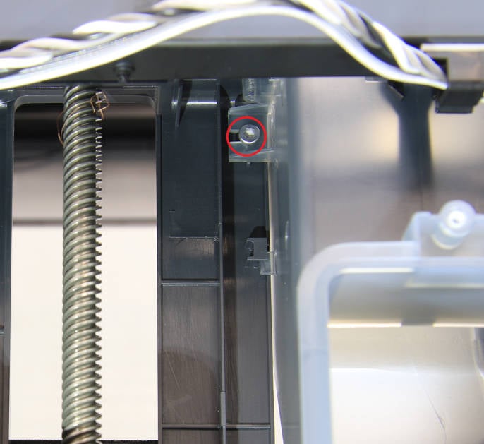 |
 |
¶ Step 4: Remove the right side panel
- First use an H2.0 Allen key to remove the 4 screws on the rear of the right side panel;
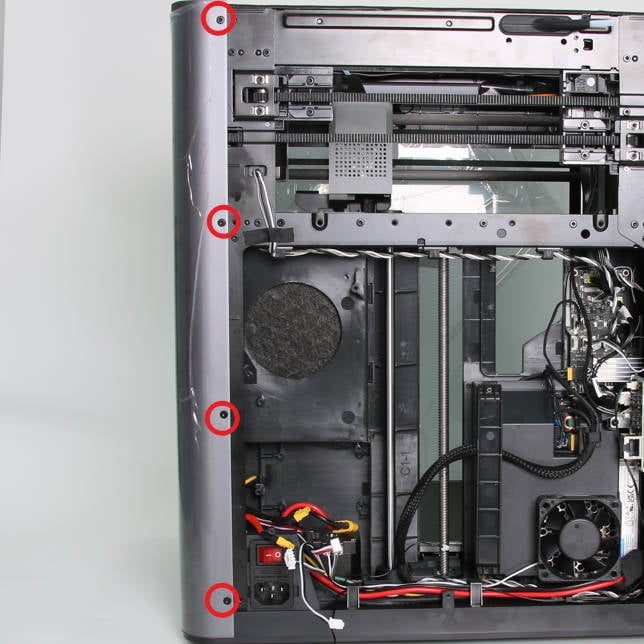
- Tear off the EVA pad and use an H2.0 Allen key to remove the 1 screw on the top of the right side panel;
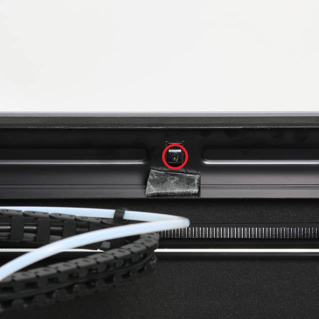
- Use an H2.0 Allen key to remove the 4 screws on the right front column;
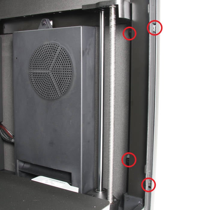
- Lay the printer on its side with the right side facing upwards, and use an H2.0 Allen key to remove the two screws at the bottom;
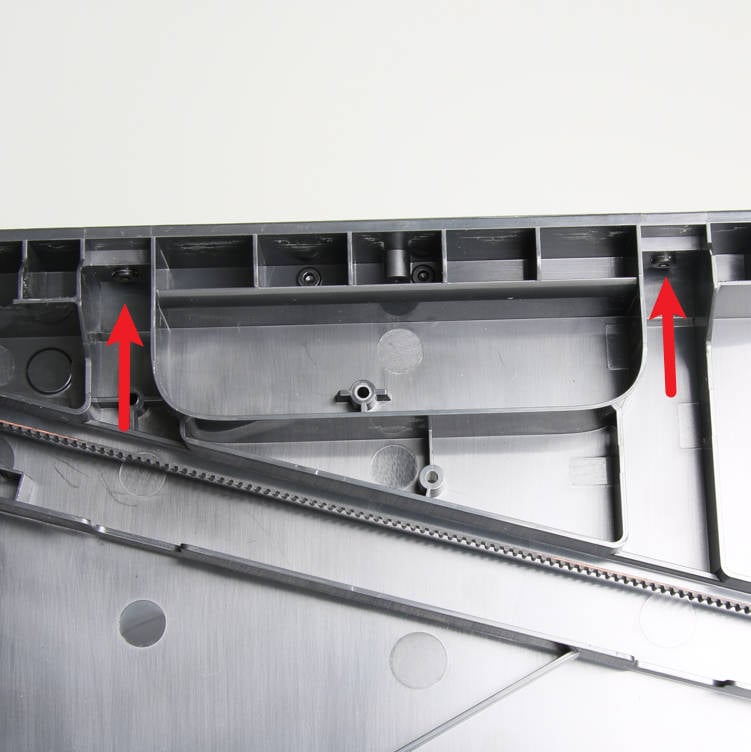
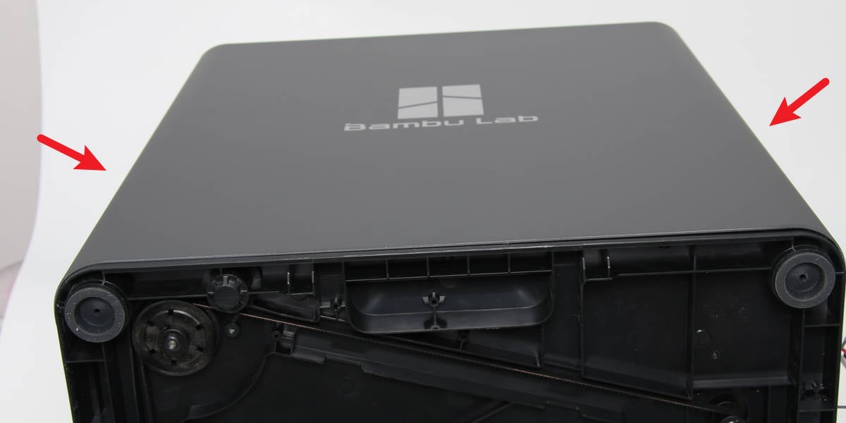
- Use force on both sides of the right side panel to remove it from the printer;
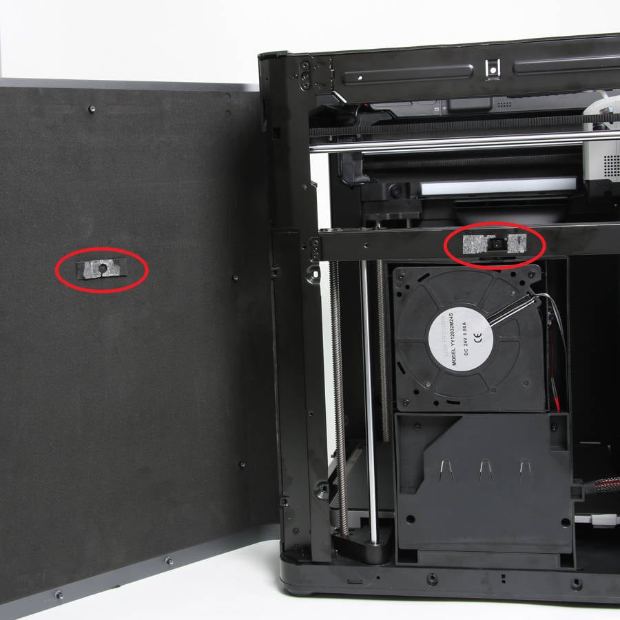
In addition to the screws, the right side panel is bonded to the printer with foam at the middle crossbeam, so it will be more difficult to remove the right side panel. It is recommended that at least two people work together.
 |
 |
¶ Step 5: Remove the network cable and AMS interface board
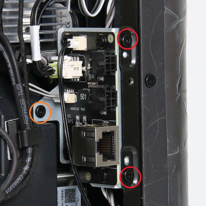
Use an H2.0 Allen key to remove the 3 screws and loosen the interface board;
¶ Step 6: Remove the air duct
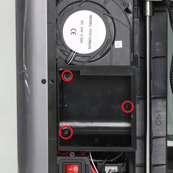
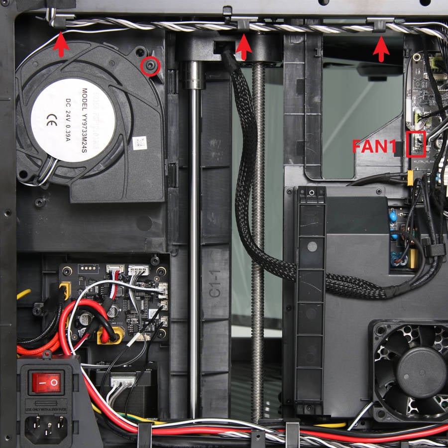
Use an H2.0 Allen key to remove the 3 screws and remove the air duct;
 |
 |
¶ Step 7: Remove the power cooling fan
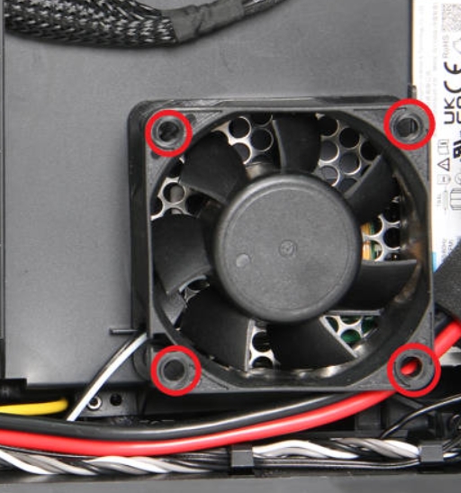
Remove the 4 screws, and remove the power cooling fan.
Simply remove the screws to take off the fan, without disconnecting the fan's cable, in order to facilitate the removal of the power protection cover.
¶ Step 8: Remove the power protection cover
- Use an H1.5 Allen key to remove the 7 screws;
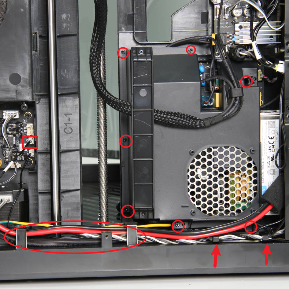
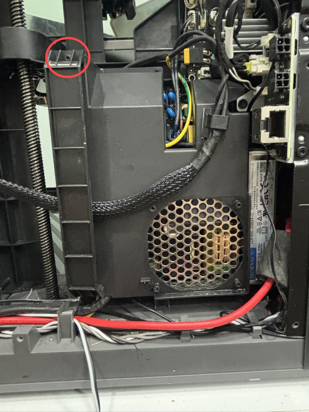
- Use an H1.5 Allen key to remove a screw above the cable, remove the heatbed cable from the routing slot, and remove the power protection cover.
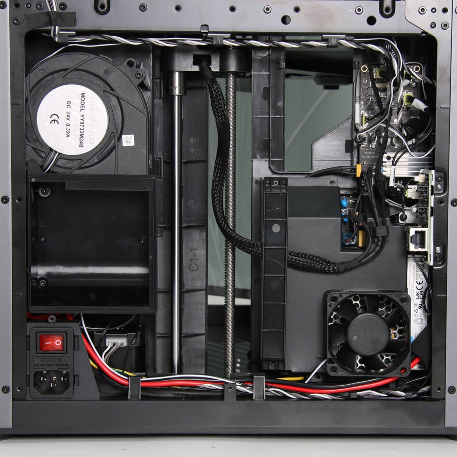
¶ Step 9: Disconnect the power cable from the power module and AC board
- Use a cross screwdriver to loosen the 3 cables in the red box in the figure below, pull them out to the left to disconnect;
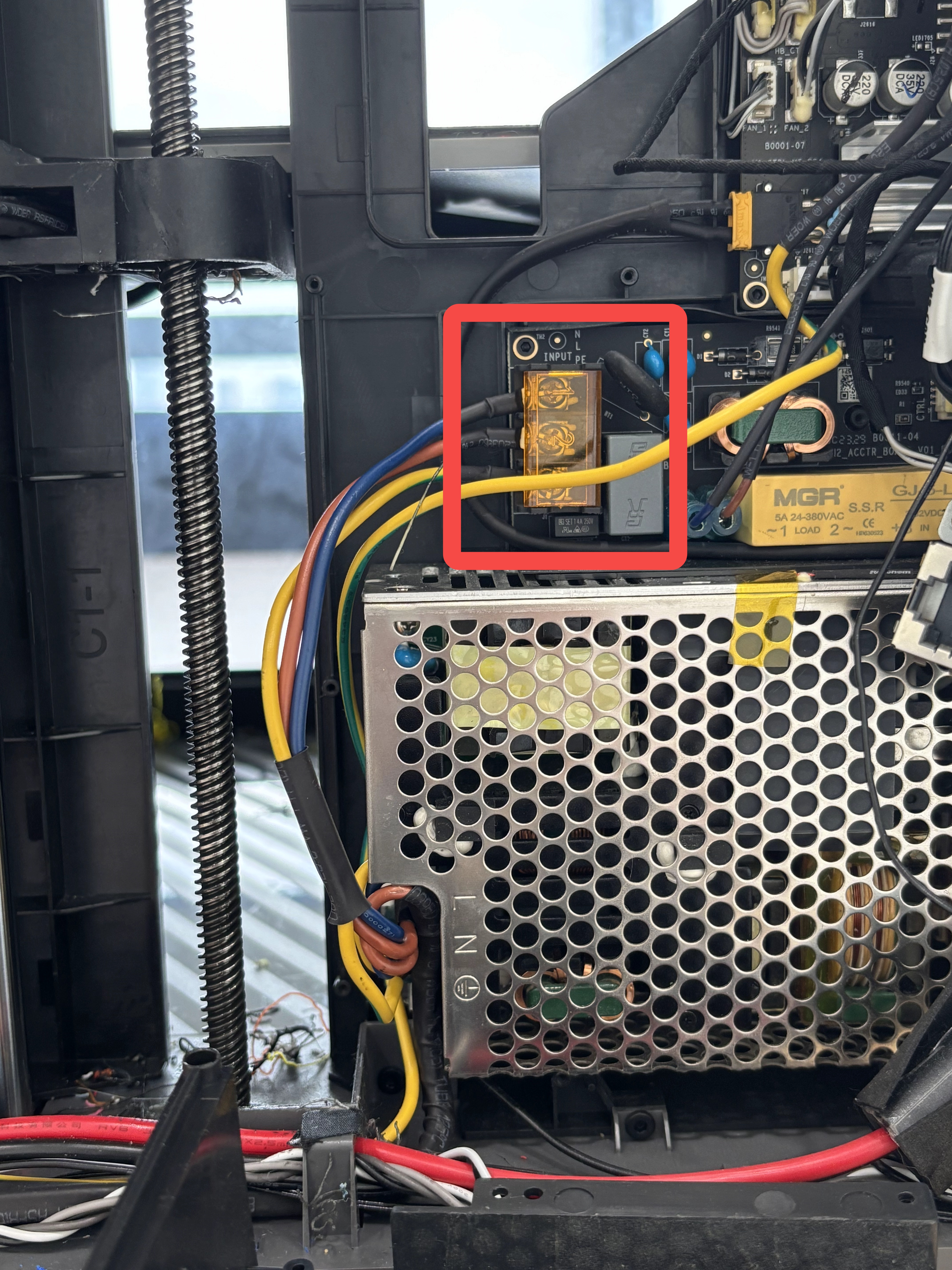
- Then disconnect the input line from the power switch, remove the rubber sleeve on the ground plug, press the unlock plug and remove the power switch ground wire.
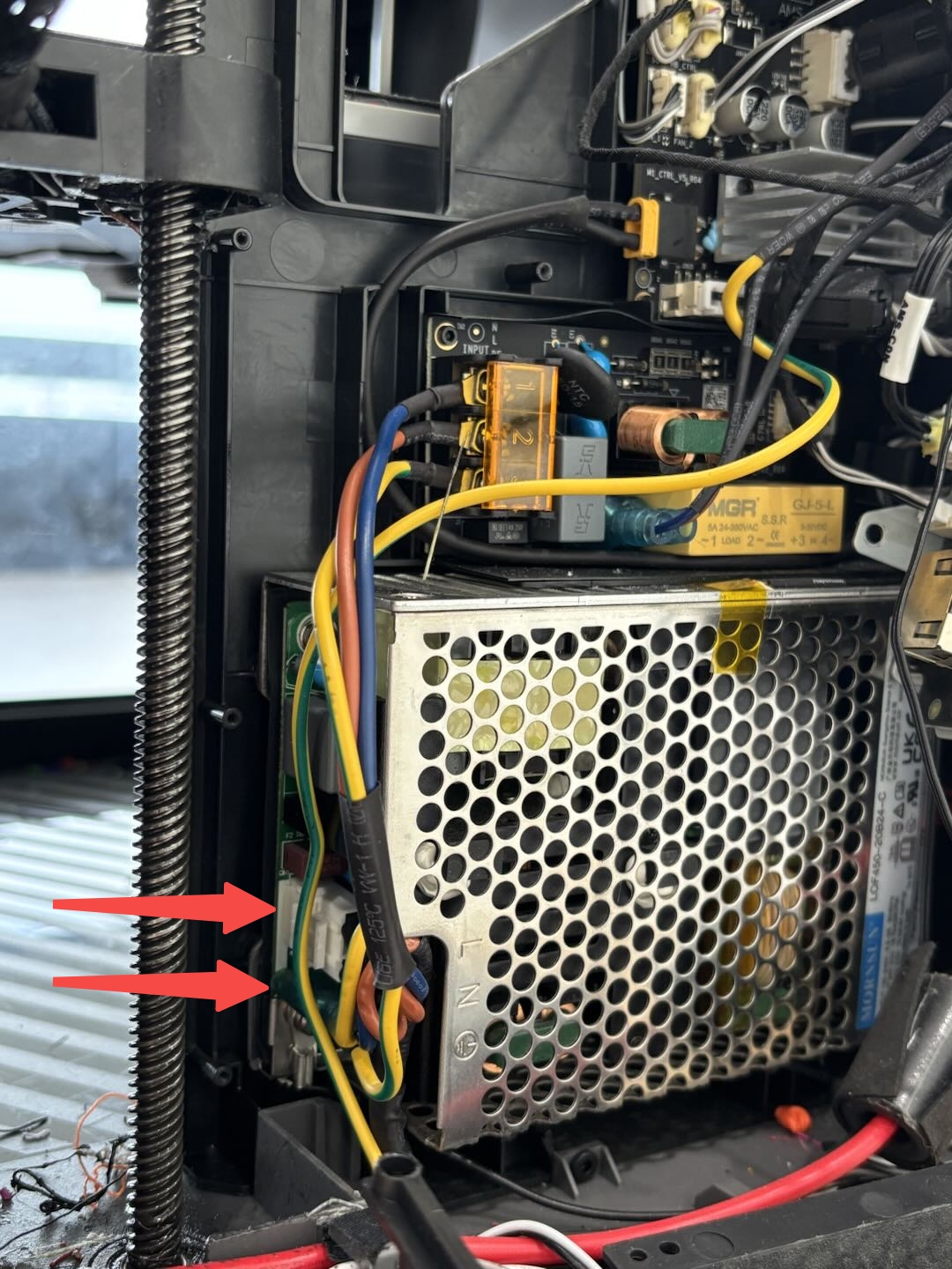
If you cannot unplug the cable directly, you can remove the power supply first and then unplug it.
¶ Step 10: Remove the ground wire
Use an H2.0 Allen key to loosen the ground wire fixing screw from the outside of the vertical beam near the power switch seat and remove the ground wire.
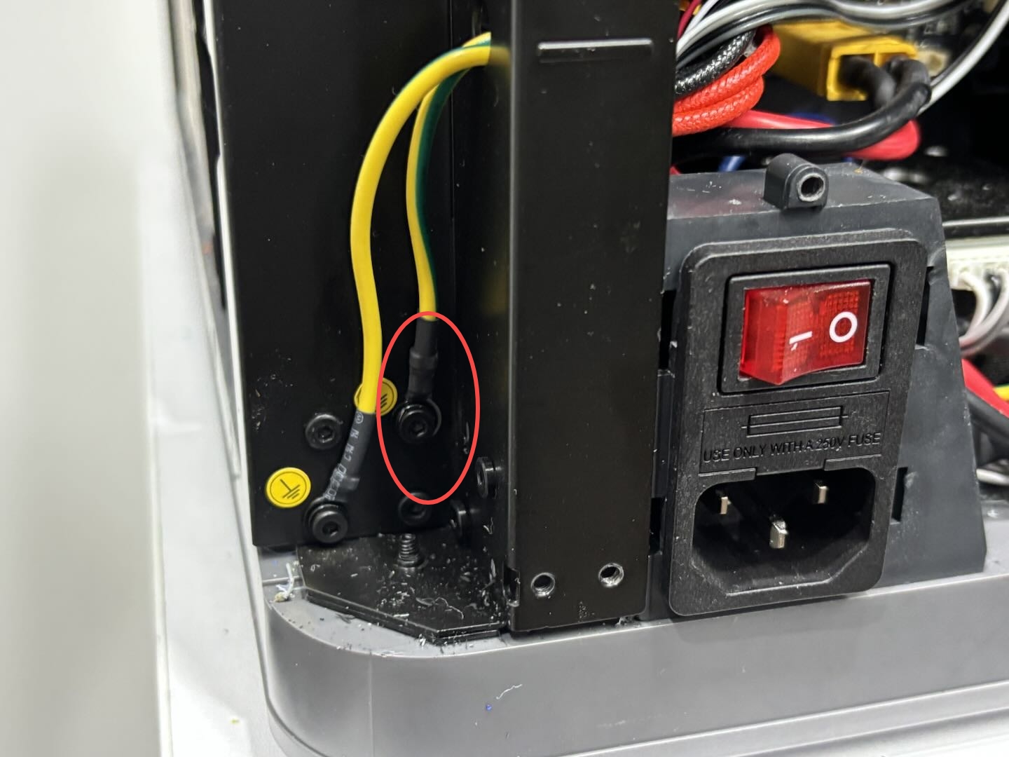
Note: There are two ground wires fixed on the vertical beam, one is for the whole machine ground (connected to the power switch assembly) and the other is for the heatbed ground. Just loosen the whole machine ground wire.
¶ Step 11: Remove the power switch
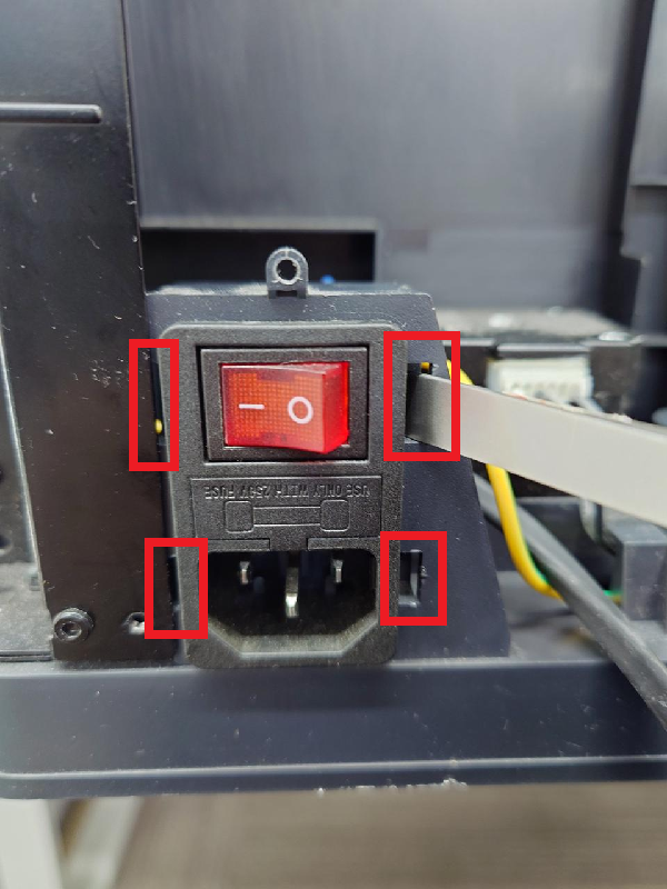
Use a flat tool to loosen the four clips from the four openings on the frame on both sides of the power switch seat, and then the power switch assembly can be loosened.
 |
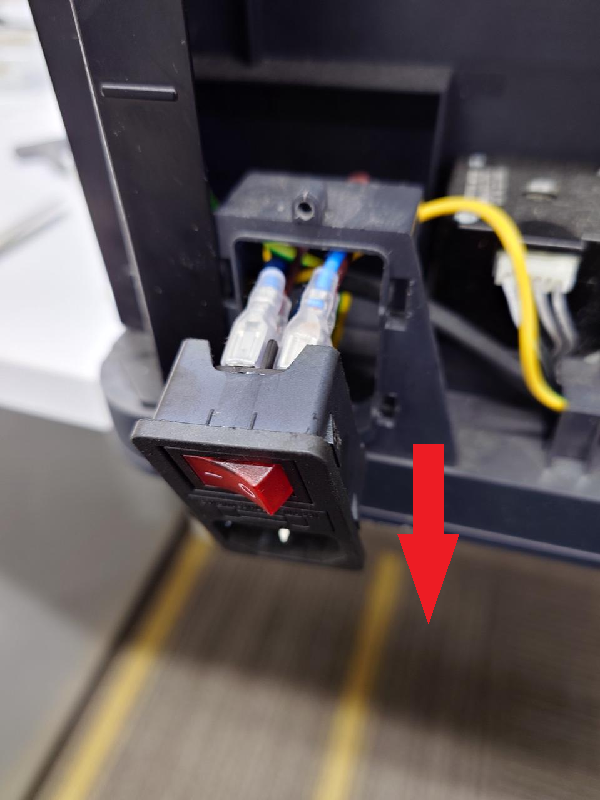 |
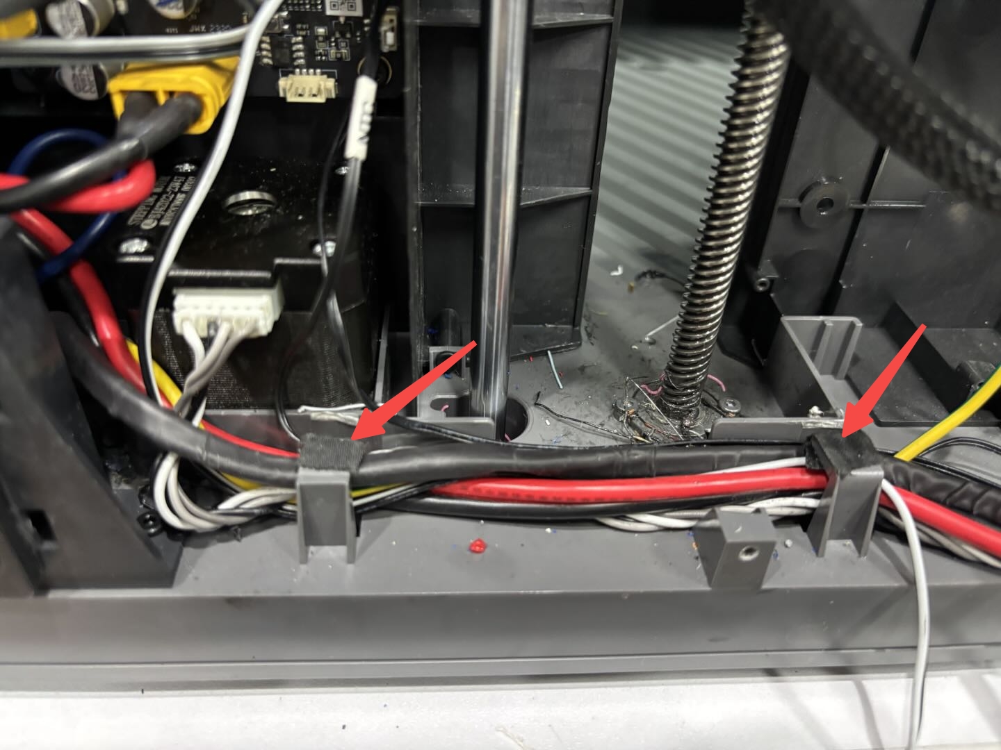
Pass the disconnected power switch cable through the clip from right to left, and then you can remove the power switch housing along with the cable to complete the disassembly.
¶ Install the power switch assembly
¶ Step 1: Install the power switch assembly
Put all the cables of the new power switch assembly through the power switch assembly frame and push it inwards, and fix the power switch assembly in place with the buckle.
¶ Step 2: Connect the ground wire
Pass the ground wire through the vertical beam and fix it on the vertical beam with an H2.0 Allen key.

Note: Grounding is an important measure to ensure electrical safety, so be sure to firmly fix the ground wire.
¶ Step 3: Connect the cable
Pass the cable from the left to the right through the cable clip and apply cable tape. Use a cross screwdriver to fix the cable connector to the power switch and AC board with a cross screw.
 |
 |
 |
Note: When connecting the top AC board, the line sequence from top to bottom should be neutral-live-ground, and the cable colors are blue-brown-yellow.
¶ Step 4: Install the power switch protection cover
- Install the power switch protection cover and tighten 7 screws;

Note: Before installing the power protection cover, please check the installation position of the power cable to avoid the screw holes.
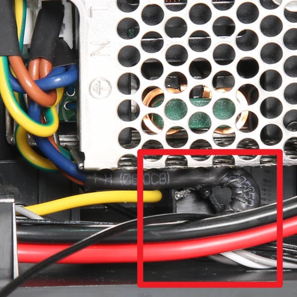
- Insert the heatbed cable into the cable routing and cable clip, and tighten 1 screw above the routing slot.

¶ Step 5: Install the power cooling fan
Install the power cooling fan, and note that the outlet direction of the fan cable should be in the lower left corner.
Fix the power cooling fan with 4 screws.

¶ Step 6: Install the network cable and AMS connector board
Reinstall the network cable and AMS connector board to the printer, and tighten the 3 screws with an H2.0 Allen wrench.

¶ Step 7: Install the air duct
Install the air duct under the chamber temperature regulator fan and tighten it with 3 screws.

¶ Step 8: Install the purge chute
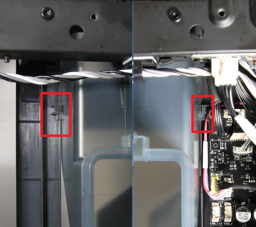
- Install the purge chute on the printer, slide the buckles on both sides of the chute into place, and make sure that the connection line is not pressed, then use the H2.0 Allen key to tighten a screw;
 |
 |
- Tighten another screw with an H1.5 Allen key.

¶ Step 9: Install the right side panel
- Install the right side panel on the printer on its side and align the installation position;

- Screw 2 screws C at the base;

- Place the printer upright, align the screw holes, and screw in 1 screw C at the top crossbeam to put the EVA pad back in place;

- Screw in 4 screws C at the right front column;

- Screw in 4 screws A behind the right side panel.

Note: When screwing the right side plate, it may be difficult to screw in the screws due to the deviation in the placement. For the 8 screws on the right front column and the rear, you can not tighten them first, and tighten them together after all the screws f are screwed in.
¶ Step 10: Install the rear panel
-
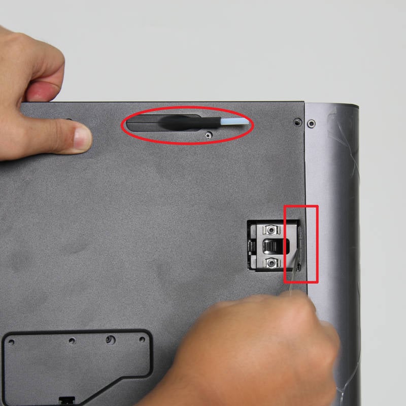
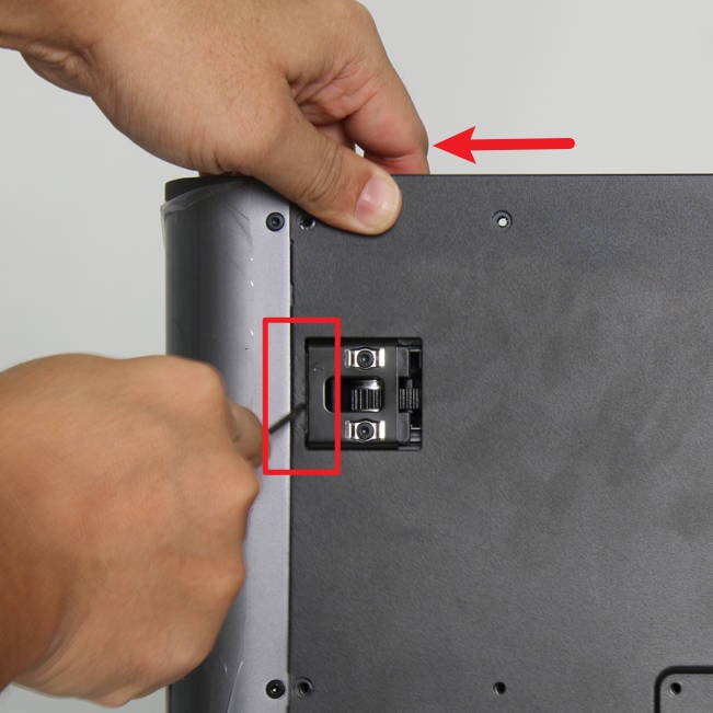
First pass the material tube bracket through the rear panel, install the position of the right tensioner in place, and use a key to press the edge to install it;
-
Then pull the rear panel to the left and install the position of the left tensioner in place. You can use a key to press the edge to assist in installation;
-
Finally, lock in 9 screws A, 4 screws B and 1 screw C to fix the rear panel.
 |
 |
 |
¶ Function confirmation
Connect the power cable and turn on the power. Run the device self-test/calibration process. If there is no error, replace the power switch assembly to complete.
¶ End Notes
We hope the detailed guide provided has been helpful and informative.
To ensure a safe and effective execution, if you have any concerns or questions about the process described in this article, we recommend submitting a Technical ticket regarding your issue. Please include a picture or video illustrating the problem, as well as any additional information related to your inquiry.