¶ What is XY motor
The X or Y motors are two same stepper motors installed on the back of the printer to drive the toolhead to move in the XY direction. There is one on the left and one on the right. For convenience, they are called A motor and B motor as shown in the picture below.
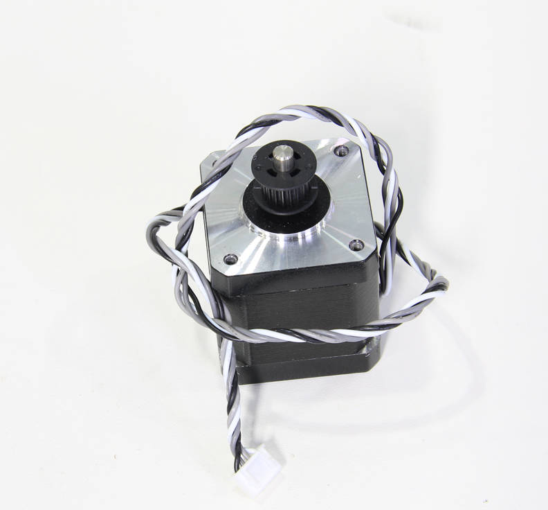 |
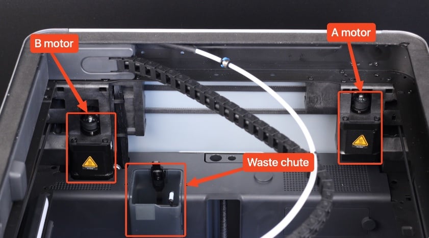
|
¶ When to use
- Motor burnout
- The after-sales team confirmed the fault of the XY motor through log analysis
¶ Tools and materials required
- H1.5 hex key
- H2.0 hex screwdriver (removing the motor requires a long screwdriver)
- Tweezers
- New XY motor
¶ Safety warning and machine state before starting operation
Turn off the power, remove the power cord, and also remove the filament buffer or AMS hub and spool holder if installed.
¶ Operational guide
¶ Step 1 - Loosen the XY belt tensioner
According to the damaged motor, refer to steps 1~5 of Replace the XY tensioner idler pulley to loosen the XY tensioner at the corresponding position.
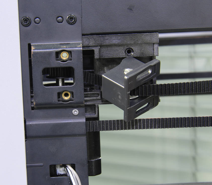
|
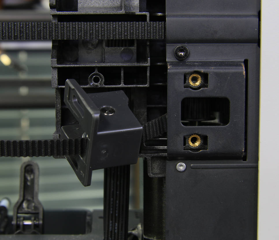
|
¶ Step 2 - Remove A motor
There are many differences in the disassembly of the A motor and the B motor, so we will describe them separately.
¶ Step 2 - 1 Remove A Motor cable
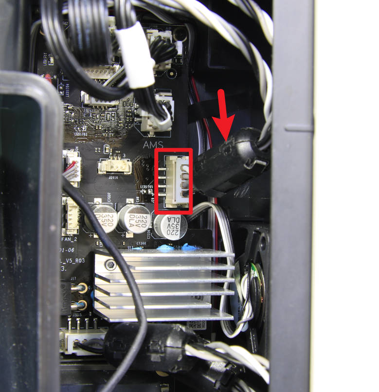
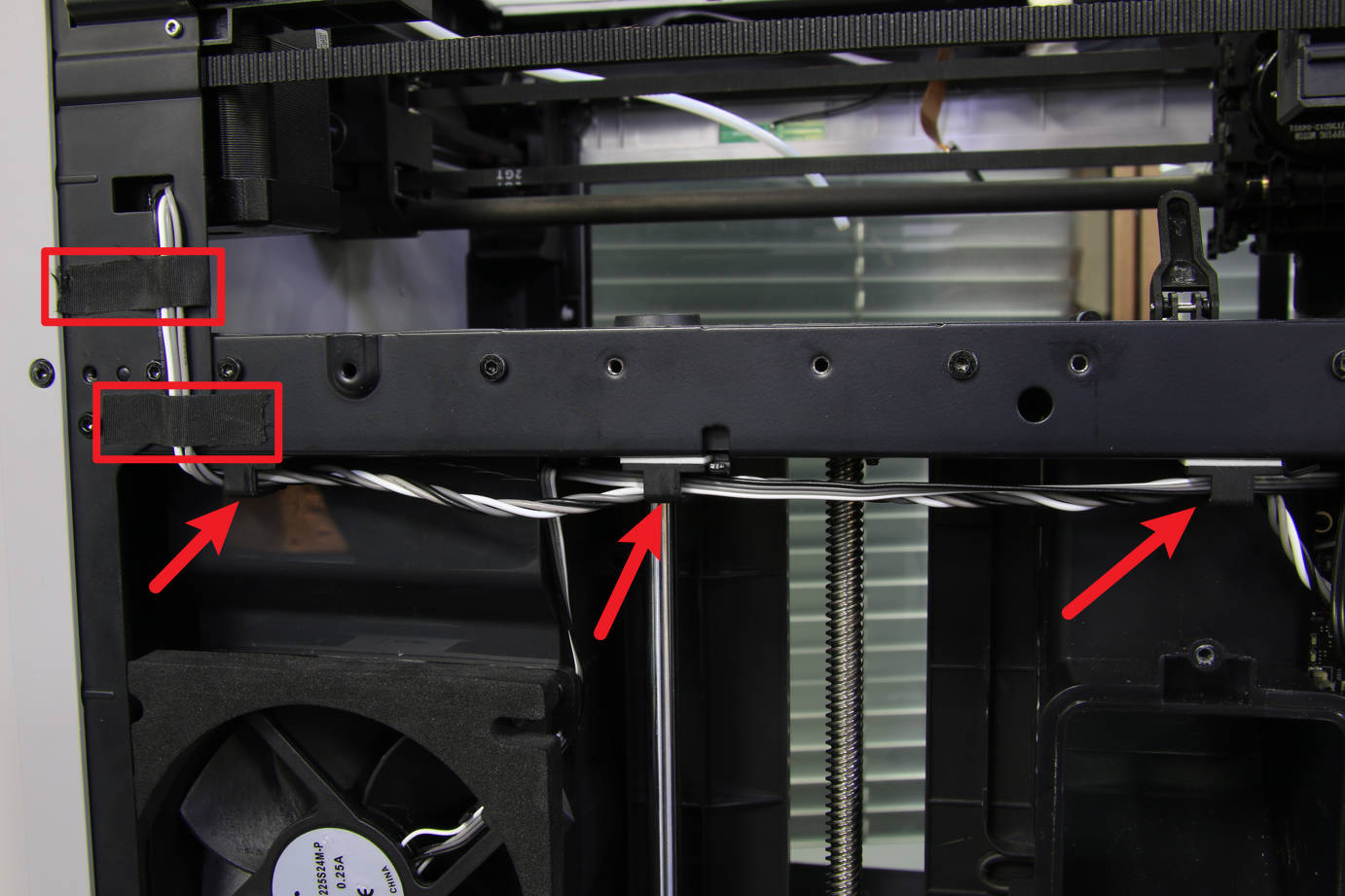
Disconnect motor A and remove the cylindrical ferrite ring on it, freeing the motor cable from the ties and tape.
 |
 |
¶ Step 2 - 2 Remove the A motor screws
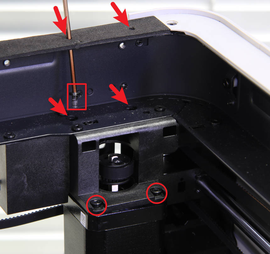
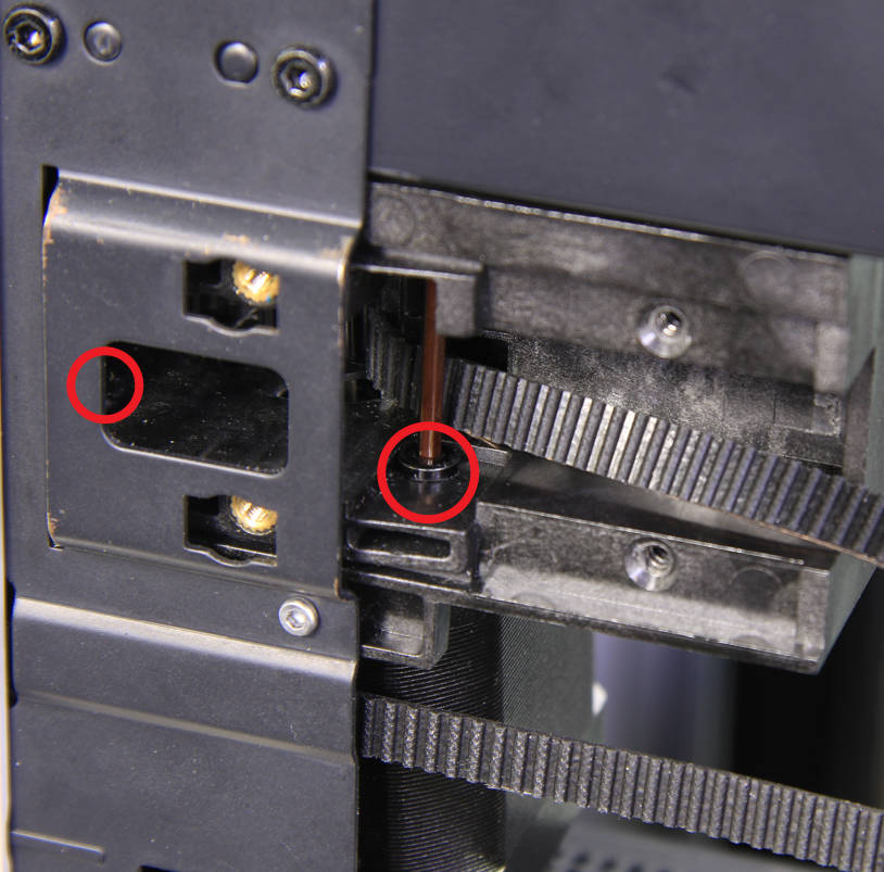
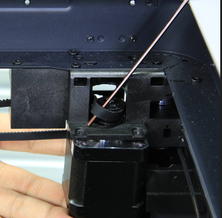
The A motor is fixed by 4 screws, remove them all. Two of the screws are clearly visible, but the other two need to be passed through the screw position from the top with a long hex screwdriver.
Note: The screws that affix the motor are relatively tight and need to be handled carefully to prevent damage to the screw heads.
 |
 |
¶ Steps 2 - 3 Remove A motor
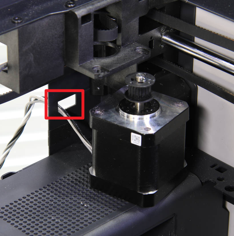
Remove the timing belt from the motor drive pulley and remove the A motor.
 |
 |
¶ Step 3 - Install the A motor
¶ Step 3 - 1 Install A motor
Pass the A motor cable through the square hole, hold the motor with your hand, and install the timing belt on the driving pulley.
 |
 |
¶ Step 3 - 2 Lock A Motor screws
Lock in the 4 screws that fix the motor. The rear two screws need to be placed on the hex screwdriver at the position of the upper beam, and then use the screwdriver to send the screws into place.
 |
 |
¶ Step 3 - 3 Connect the A motor cable
Arrange the motor cable as shown in the figure below, install the cylindrical ferrite ring, and then connect the cable to the connector on the MC board.
 |
 |
¶ Step 4 - Remove the B motor
The disassembly and assembly of the B motor are more complicated than that of the A motor, and some more parts need to be removed, such as the excess chute, the AP board cover, and the inner shield assembly.
¶ Step 4 -1 Removing the excess chute
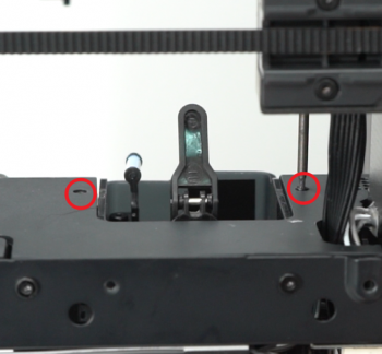
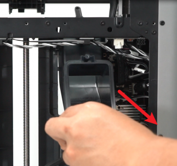
Undo the 2 screws located at each side of the excess chute. once done, take out the excess chute.
 |
 |
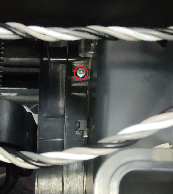
Note: We later added a screw on the left side, which can be unscrewed with an H2.0 hex key.
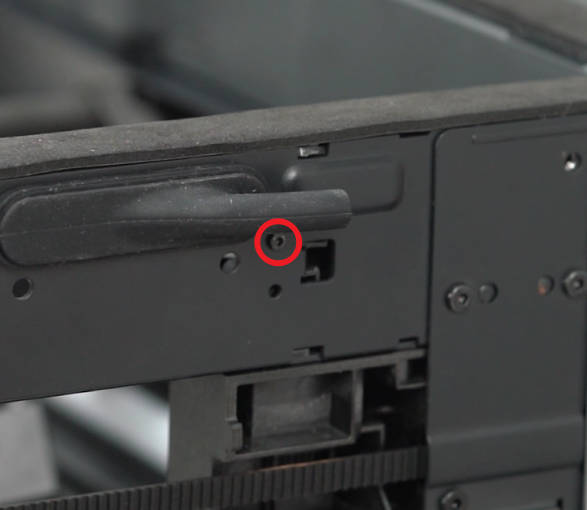
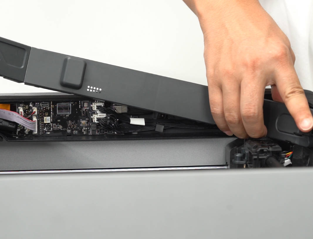
¶ Step 4 - 2 Remove the AP board cover
Remove 1 screw with an H1.5 hex key, open the AP board cover and remove it.
 |
 |
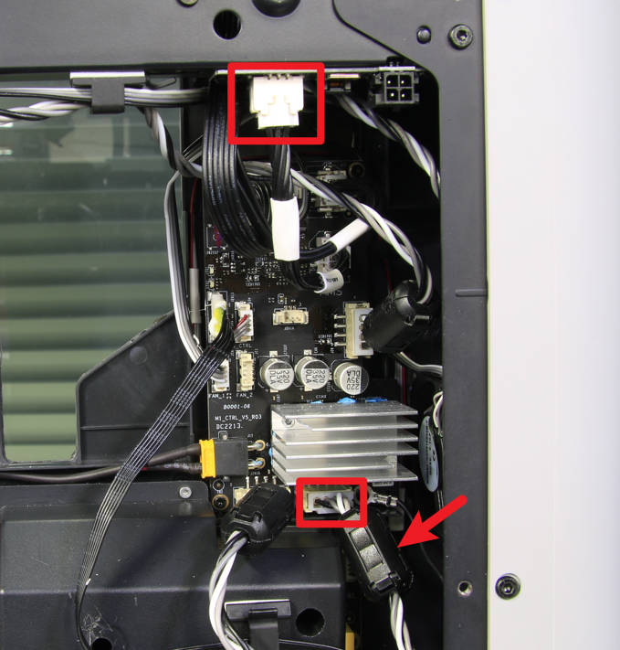
¶ Steps 4 - 3 Disconnect the cables
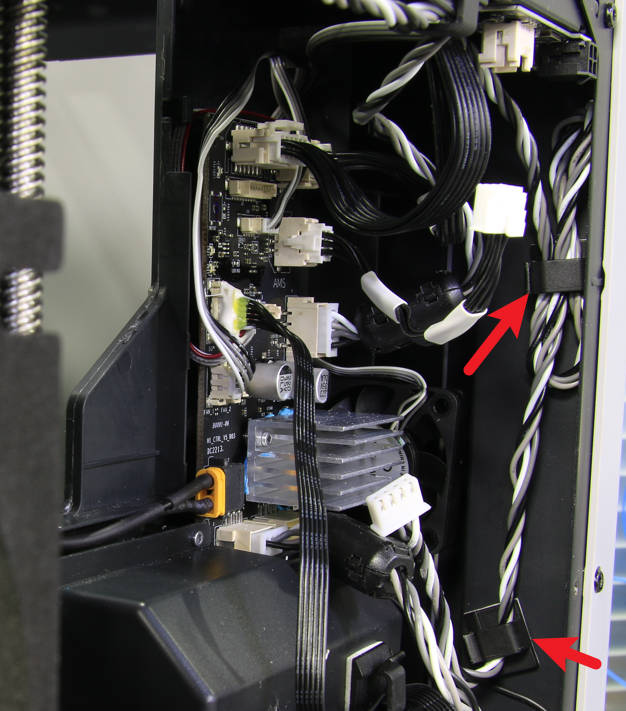
Disconnect the B motor cable and the AMS interface board cable, remove the cylindrical ferrite ring on the motor cable, and release the cable from the cable ties.
 |
 |
¶ Steps 4 - 4 Lower the heat bed
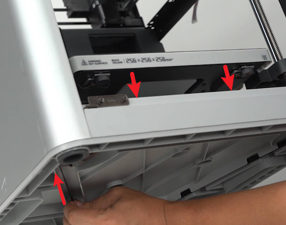
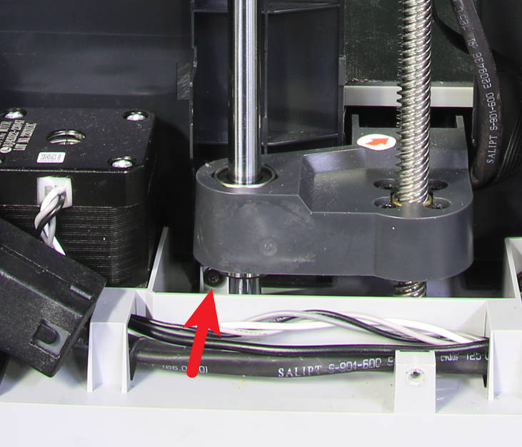
Tilt the printer, lower the heat bed by moving the Z-axis belt, and lower it as low as possible without affecting the removal and installation of the screw.
|
|
¶ Steps 4 - 5 Loosen the power socket
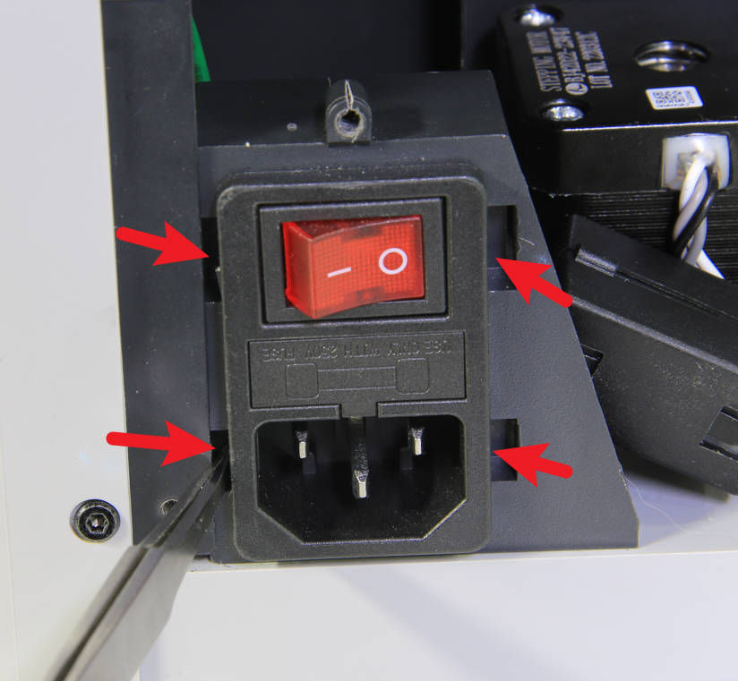
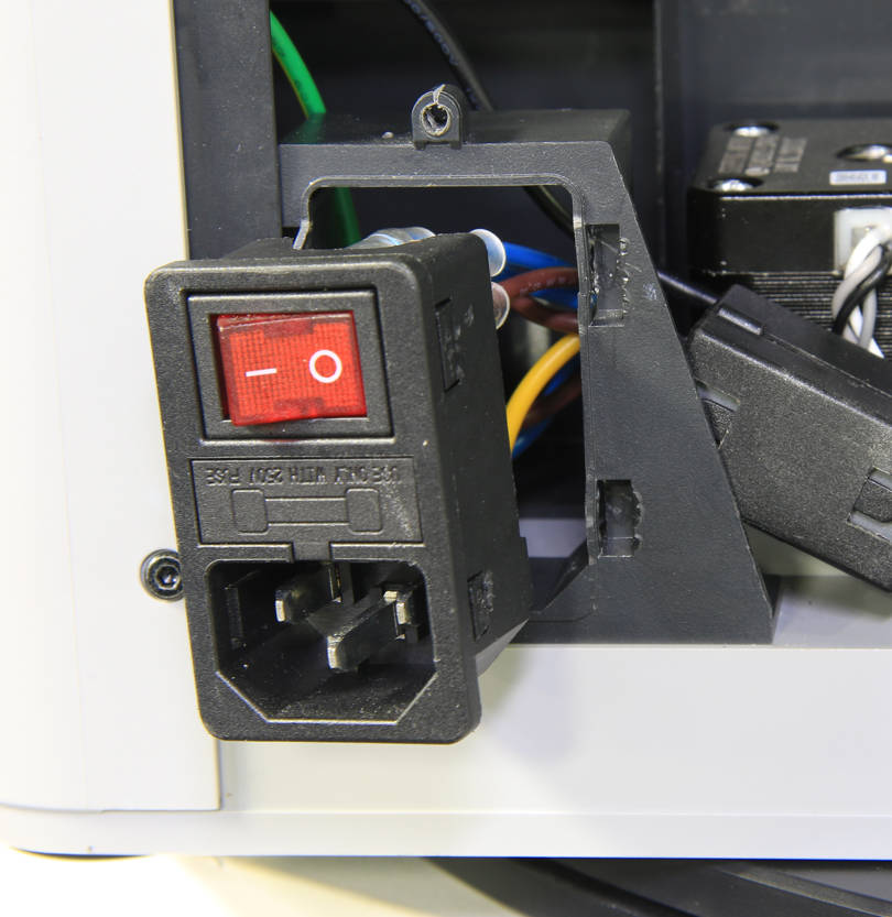
Pry the power socket with tweezers to loosen it out.
 |
 |
¶ Steps 4 -6 Loosen the inner shield
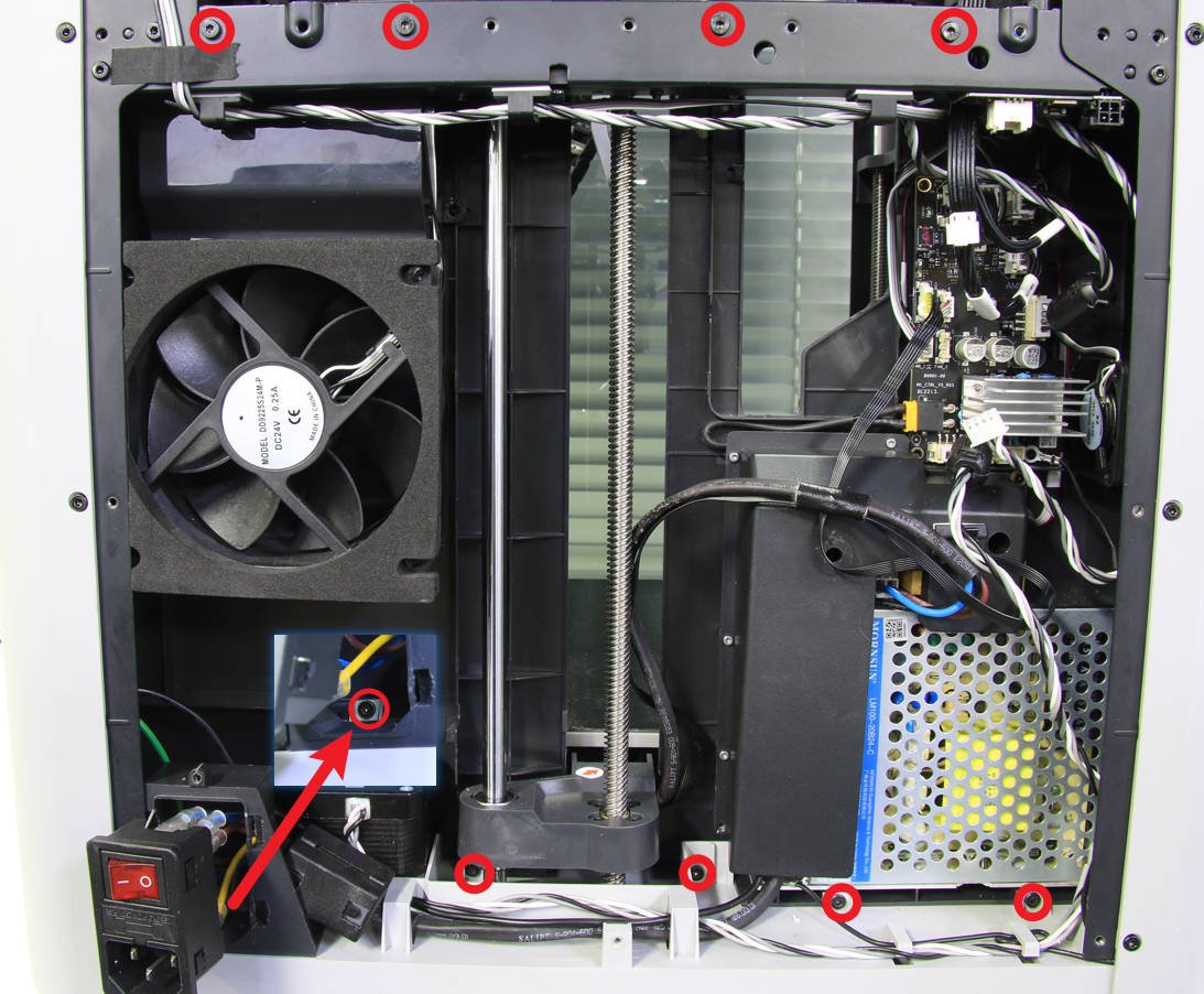
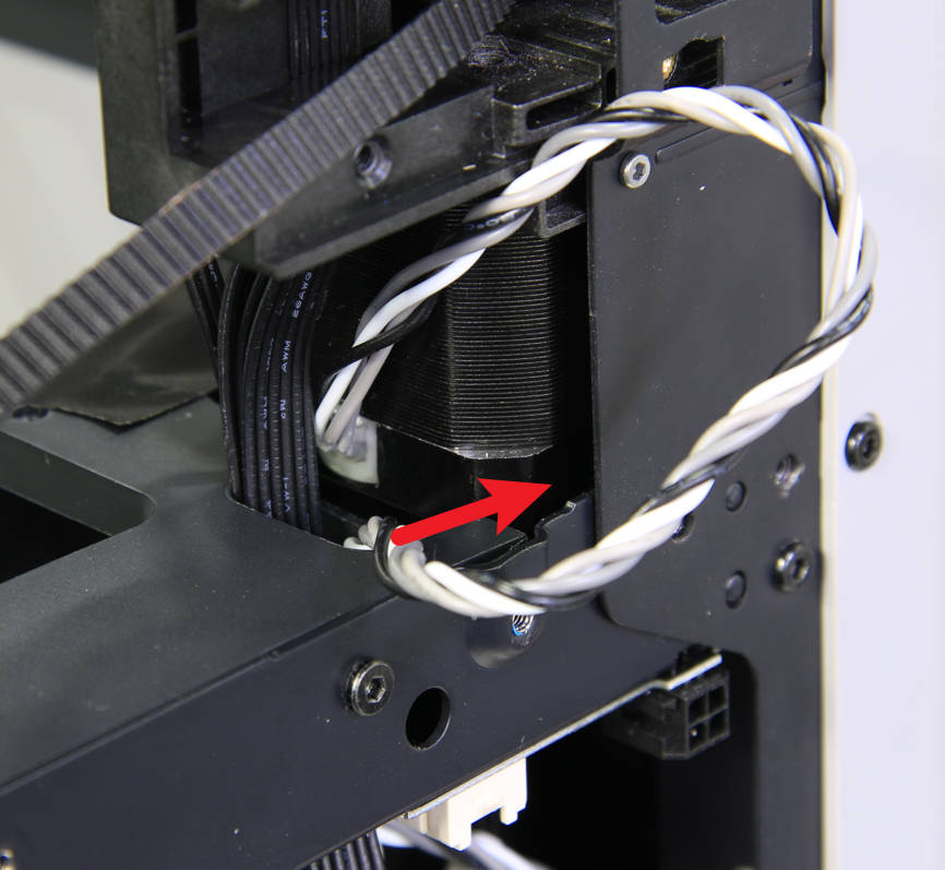
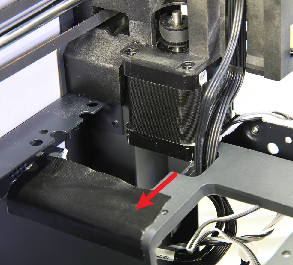
Remove the 9 screws that fix the inner shield with an H2.0 hex screwdriver, pull out the B motor cable from the cable hole on the inner shield, and then separate the inner shield from the rear beam to free up space for the B motor.
 |
 |
 |
¶ Steps 4 - 7 Remove B motor screws
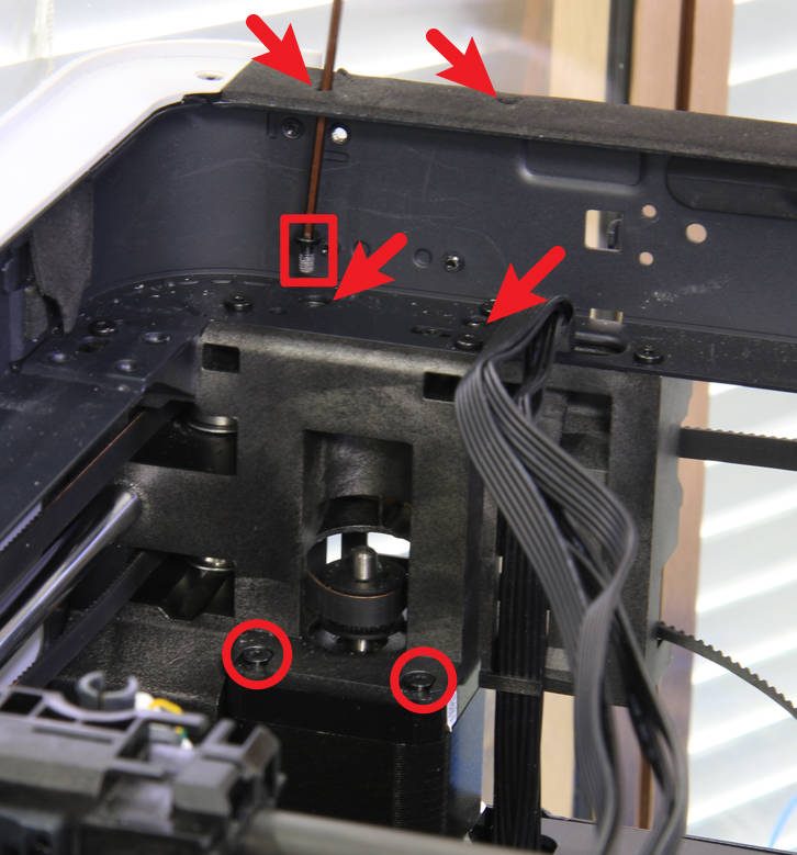
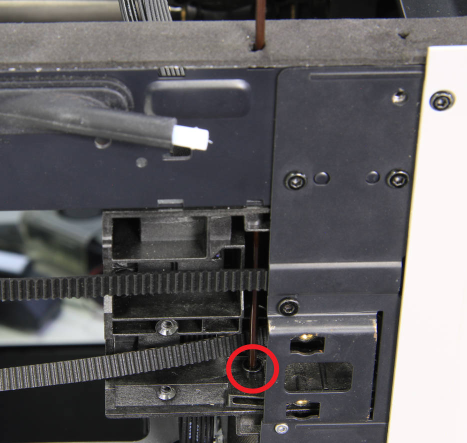
The B motor is also affixed with 4 screws.Two of the screws are clearly visible, but the other two need to be passed through the screw position from the top with a long hex screwdriver.
Note: The screws that fix the motor are relatively tight and need to be handled carefully to prevent damage to the screw heads.
 |
 |
¶ Steps 4 - 8 Remove the B motor
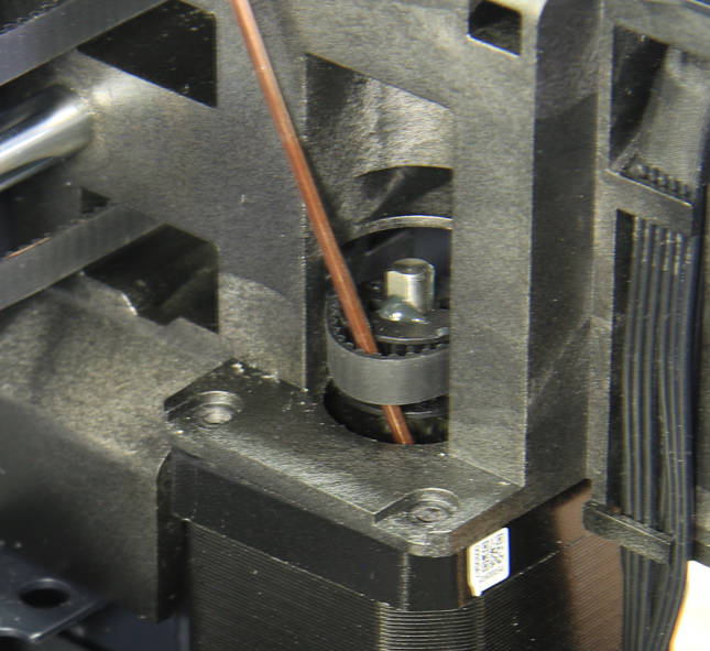
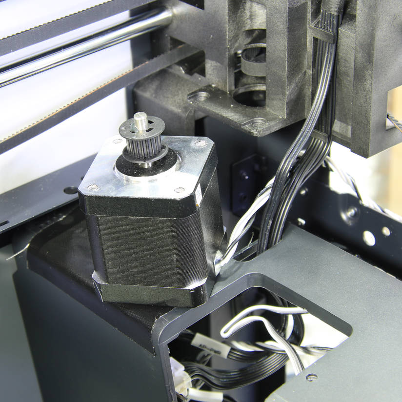
Remove the timing belt from the motor drive pulley and remove the B motor.
 |
 |
¶ Step 5 - Install the B motor
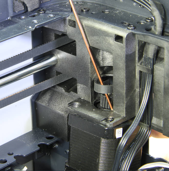
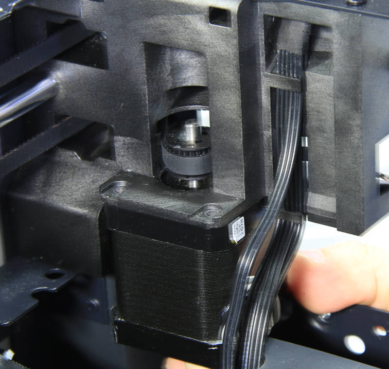
¶ Step 5-1 Install B motor
Install the B motor in place and install the timing belt to the motor drive pulley.
 |
 |
¶ Step 5 -2 Lock B motor screws
Lock in the 4 screws that fix the motor. One of the rear screws needs to be placed on the hex screwdriver at the position of the upper beam, and then send the screw to the position with the screwdriver. The other rear screw needs to be placed directly in the screw hole, and then tightened with a screwdriver.
 |
 |
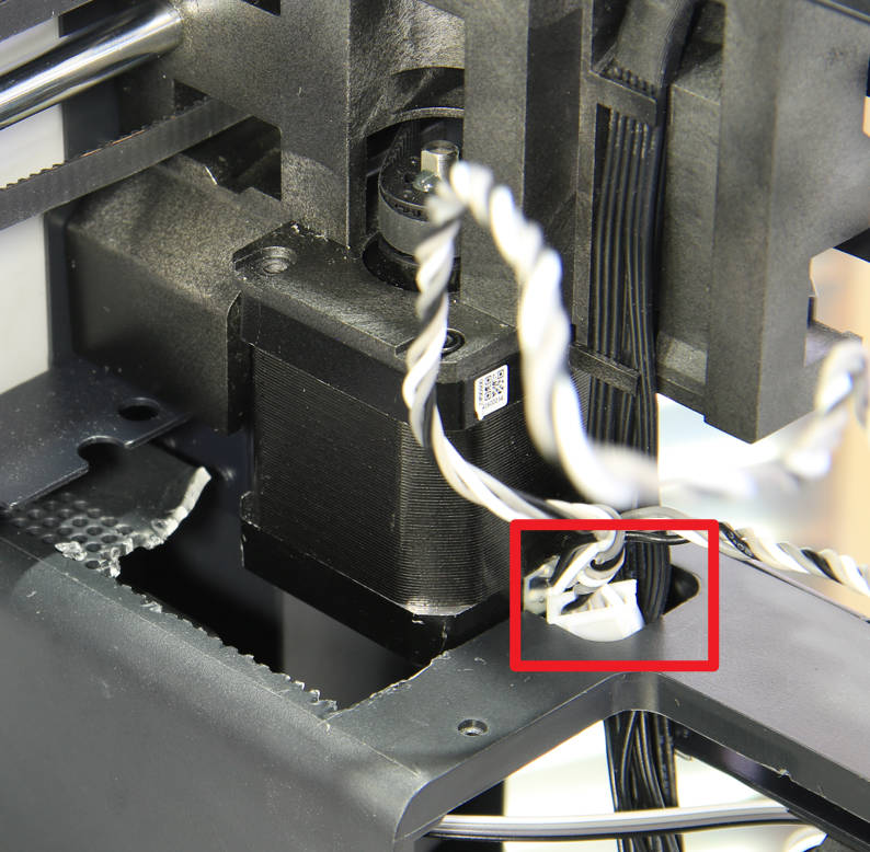
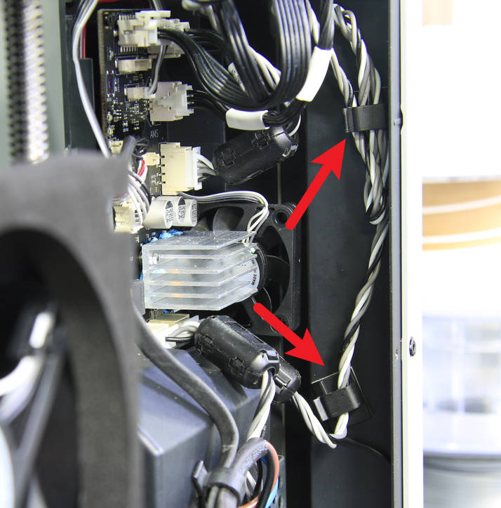
¶ Step 5 -3 Connect the cables
Pass through the motor cable, install the cylindrical ferrite ring, connect the motor cable to the connection port of the B motor on the MC board, connect the AMS interface board cable, and arrange the cables as shown in the picture below.
 |
 |
 |
¶ Steps 5-4 Install the inner shield
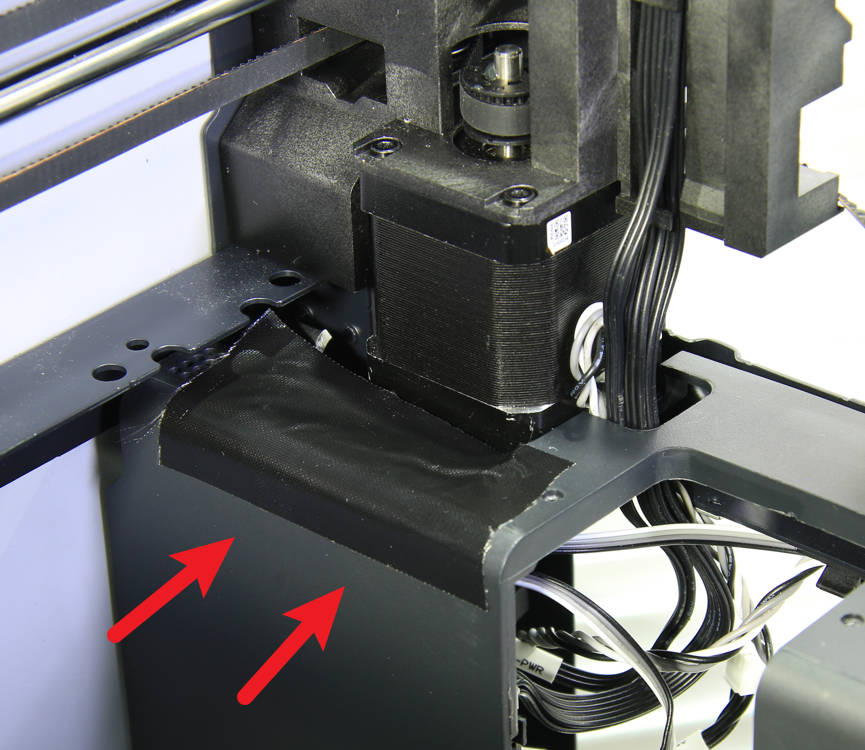
Place back and fit the inner shield to the rear beam and lock in 9 screws to affix it.
 |
 |
¶ Steps 5-5 Mount the power socket
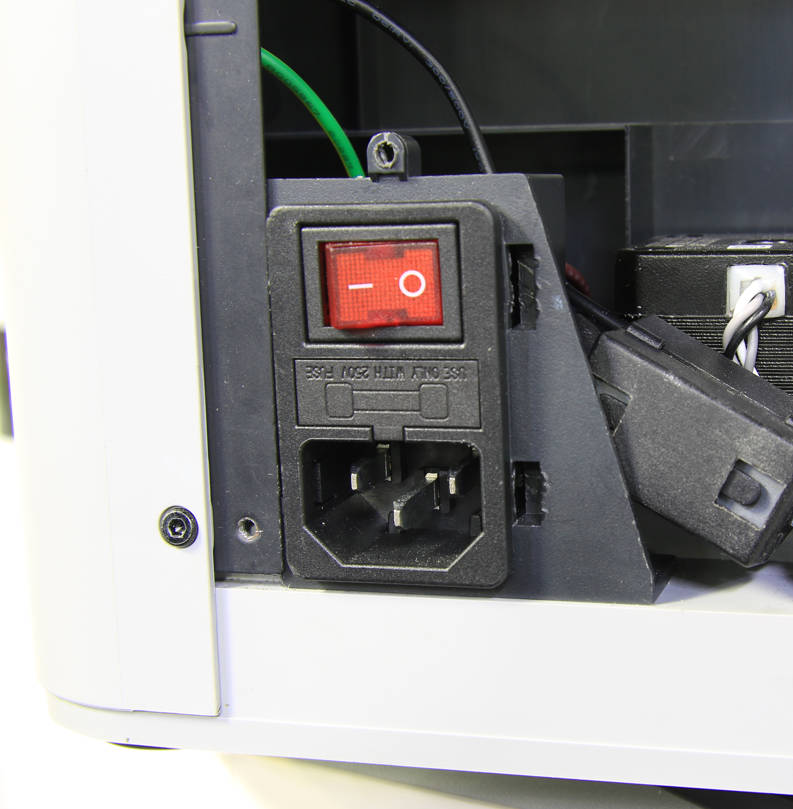
Mount the power socket back into place.
¶ Step 5 -6 Install the AP board cover
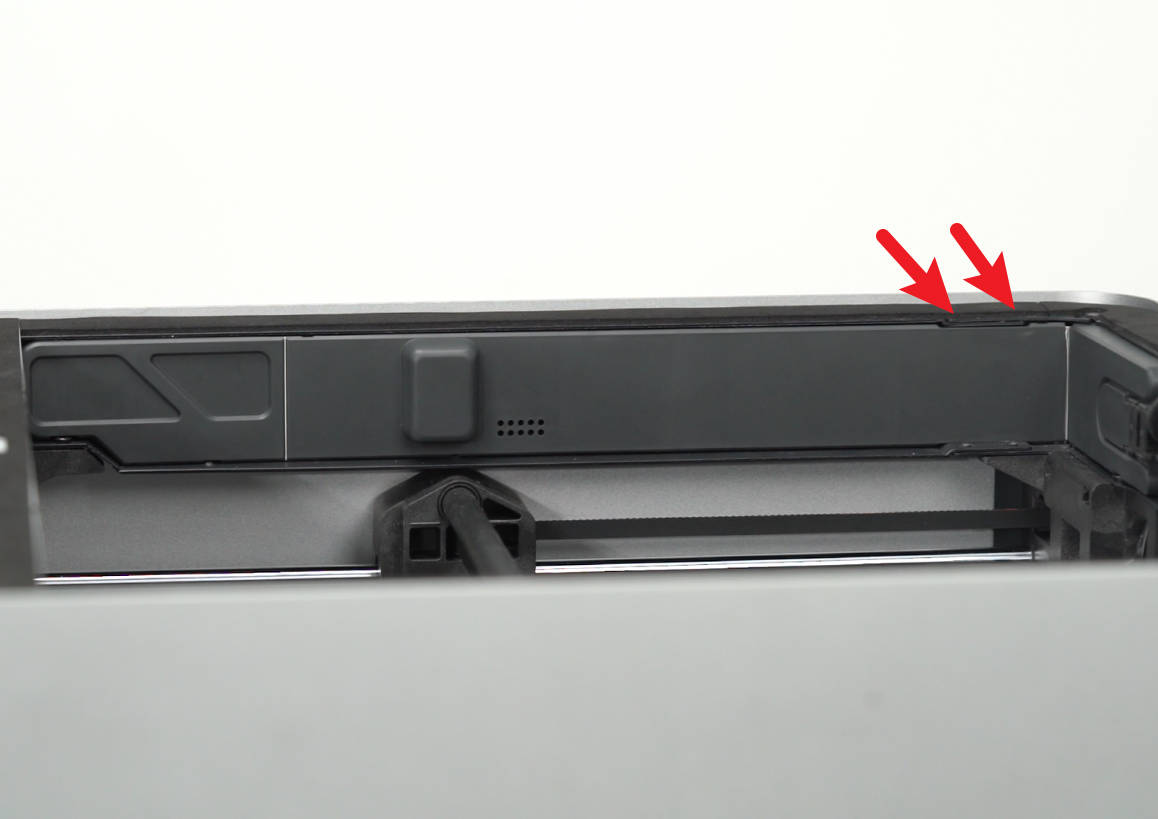
As shown in the figure below, align the positions indicated by the arrows first, and then install the AP board cover. Lock in 1 screw on the back of the printer to affix the AP board cover.
 |
 |
¶ Step 5 -7 Install the excess chute
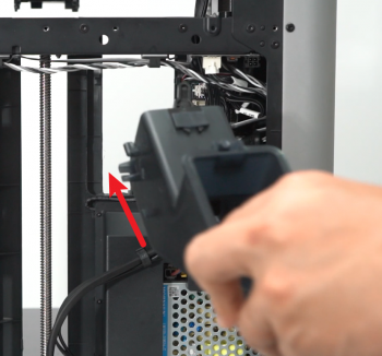
Install the excess chute by sliding it back in its position, paying attention to the protruding tabs on both sides of the chute. Finally, secure it in place with 2 screws at each side of the top of the chute.
 |
 |
¶ Step 6 - Install the XY tensioners, assemble the printer
Refer to steps 9~13 of Replace the XY tensioner idler pulley to install the tensioners, assemble the printer, and complete the XY timing belt tensioning.
¶ How to verify completion/success
- Power ON the printer
- Run a Device self-test operation as shown below and if no errors occur, the replacement was successful.
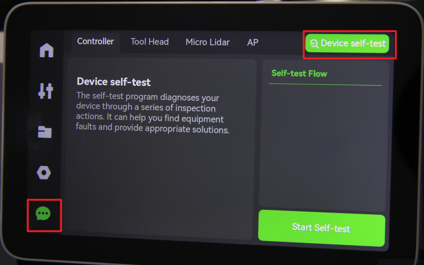
Should you come across any issues, first retrace your steps and retention the belt to try again. If problems persist, contact the customer support team for further assistance.