¶ Extruder Motor
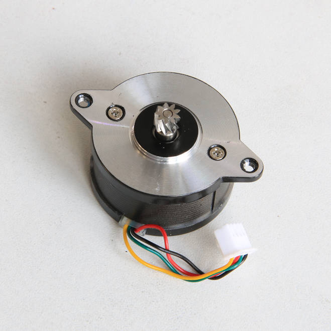
The extruder motor, installed on the tool head, drives the extruder movement. It's a 36-series circular stepper motor.
¶ When to use
- The motor is damaged and unable to function.
- The after-sales team confirmed the extruder motor's fault through log analysis.
¶ Tools
- New extruder motor
- H2.0/H1.5 hex key
- Silicone glue

¶ Safety Warning
IMPORTANT!
It's crucial to power off the printer before conducting any maintenance work, including work on the printer's electronics and tool head wires. Performing tasks with the printer on can result in a short circuit, leading to electronic damage and safety hazards.
During maintenance or troubleshooting, you may need to disassemble parts, including the hotend. This exposes wires and electrical components that could short circuit if they contact each other, other metal, or electronic components while the printer is still on. This can result in damage to the printer's electronics and additional issues.
Therefore, it's crucial to turn off the printer and disconnect it from the power source before conducting any maintenance. This prevents short circuits or damage to the printer's electronics, ensuring safe and effective maintenance. For any concerns or questions about following this guide, open a new ticket in our Support Page and we will do our best to respond promptly and provide the assistance you need.
¶ Operational guide
¶ Step 1 - Remove the TH board assembly
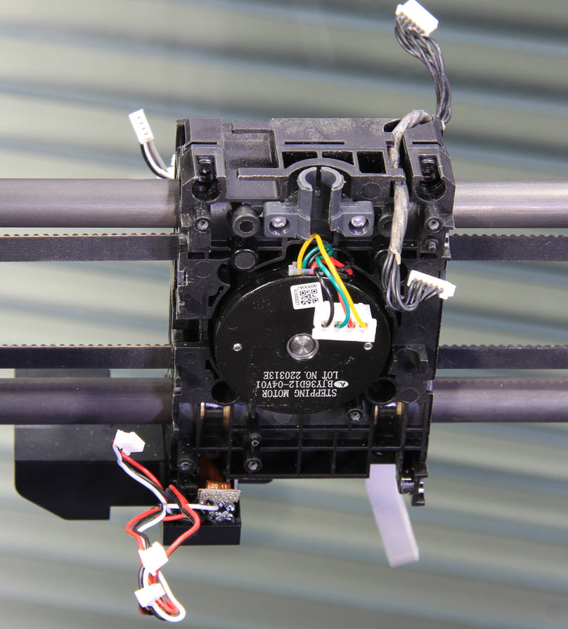
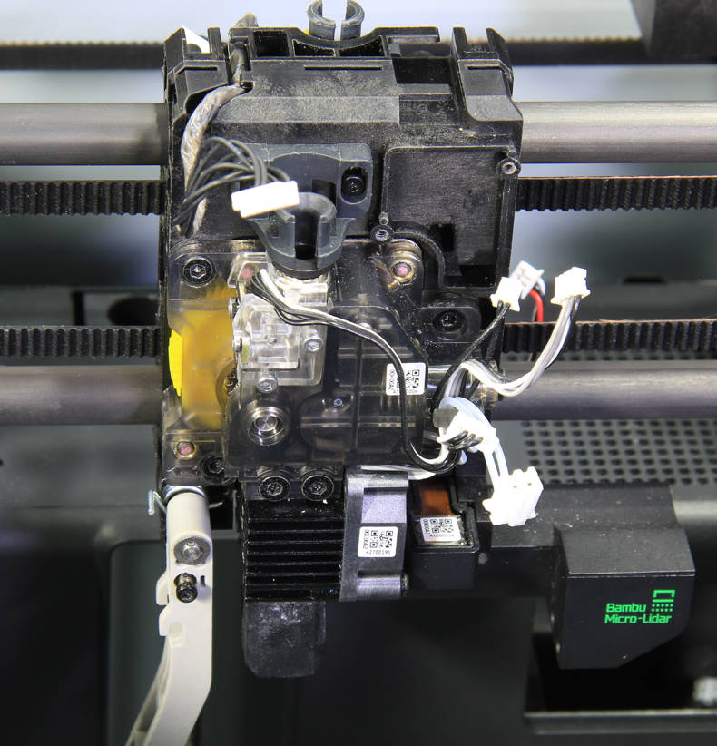
Refer to the video on Replace the TH board assembly to disassemble to toolhead and remove the TH board assembly.
 |
|
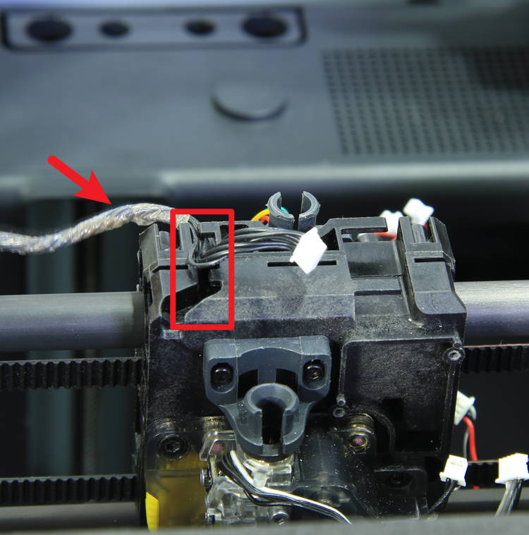
¶ Step 2 - Remove the LED light cable
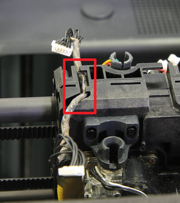
Remove the tool head system LED light cable.
|
 |
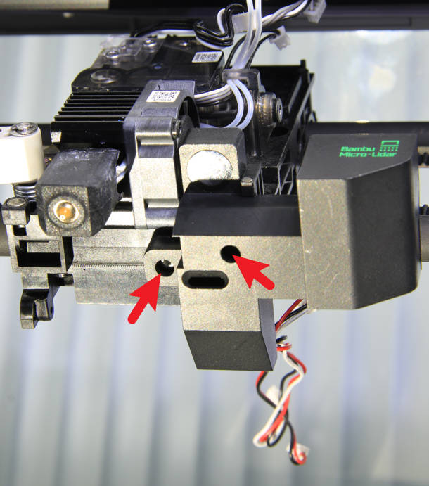
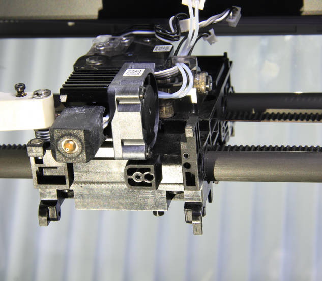
¶ Step 3 - Remove the bambu micro lidar
Remove 2 screws with an H1.5 hex key and remove the micro lidar assembly.
|
|
 |
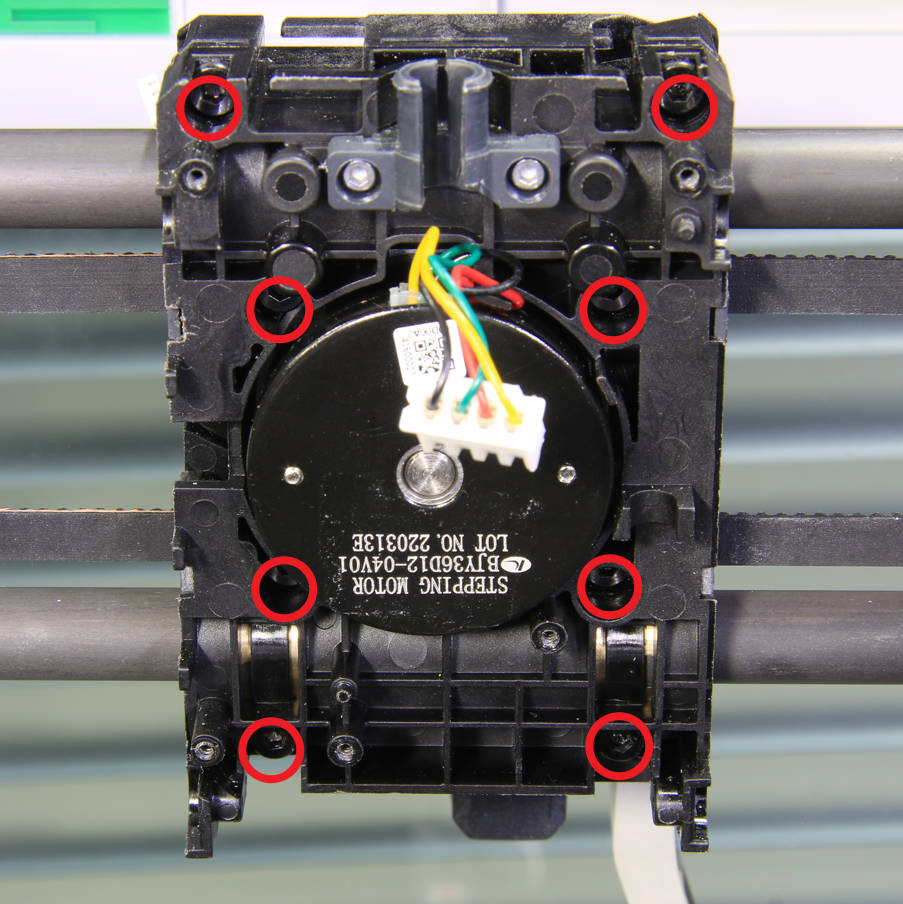
¶ Step 4 - Remove 8 screws
Remove 8 screws with an H2.0 hex key in sequence.
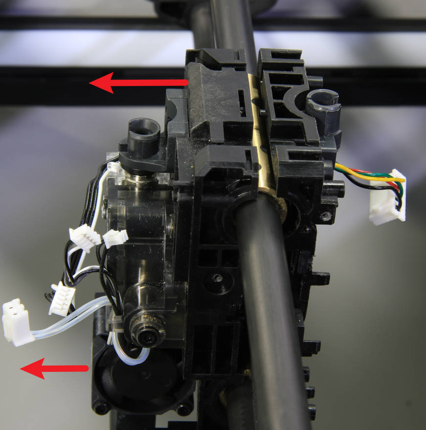
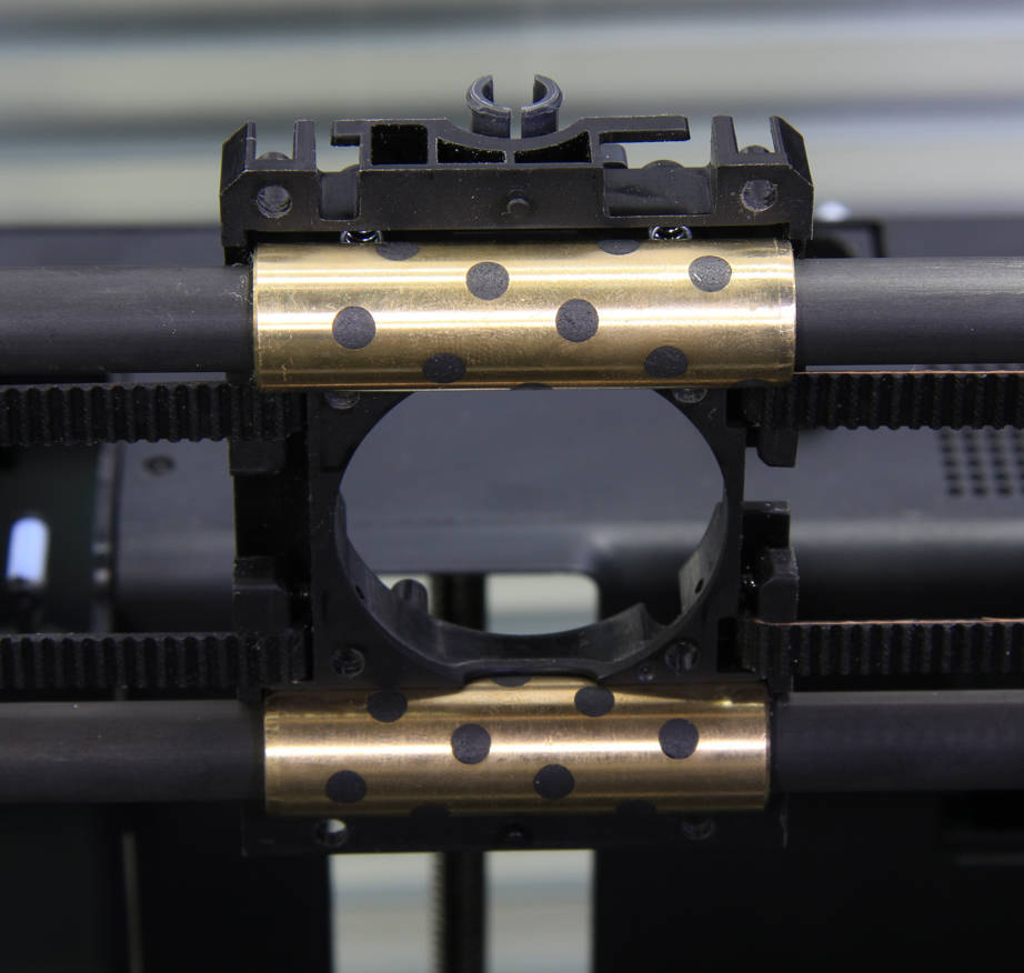
¶ Step 5 - Remove the front cover assembly of the toolhead slider
Remove the front cover assembly (with the extruder) of the toolhead.
 |
 |
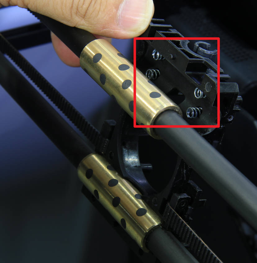
Note: There are four springs attached to the back cover of the tool head slider at the upper position of the copper sleeve to prevent it from falling off.
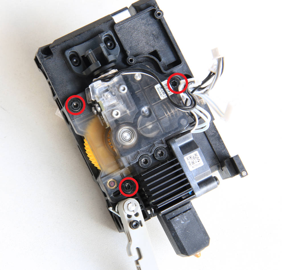
¶ Step 6 - Remove the extruder
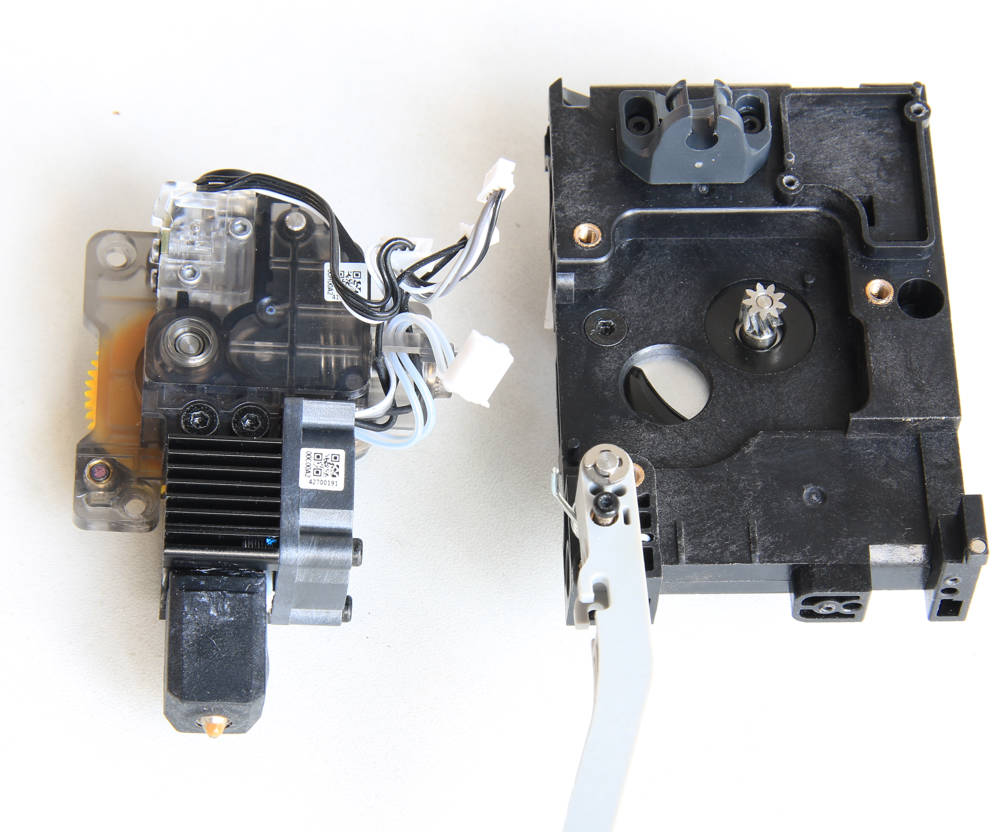
Remove the 3 screws with an H2.0 hex key, and remove the extruder and the hot end.
|
|
¶ Step 7 - Remove the extruder motor
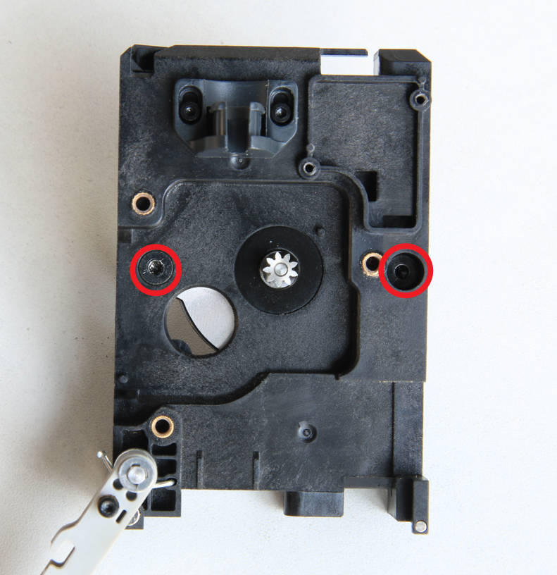
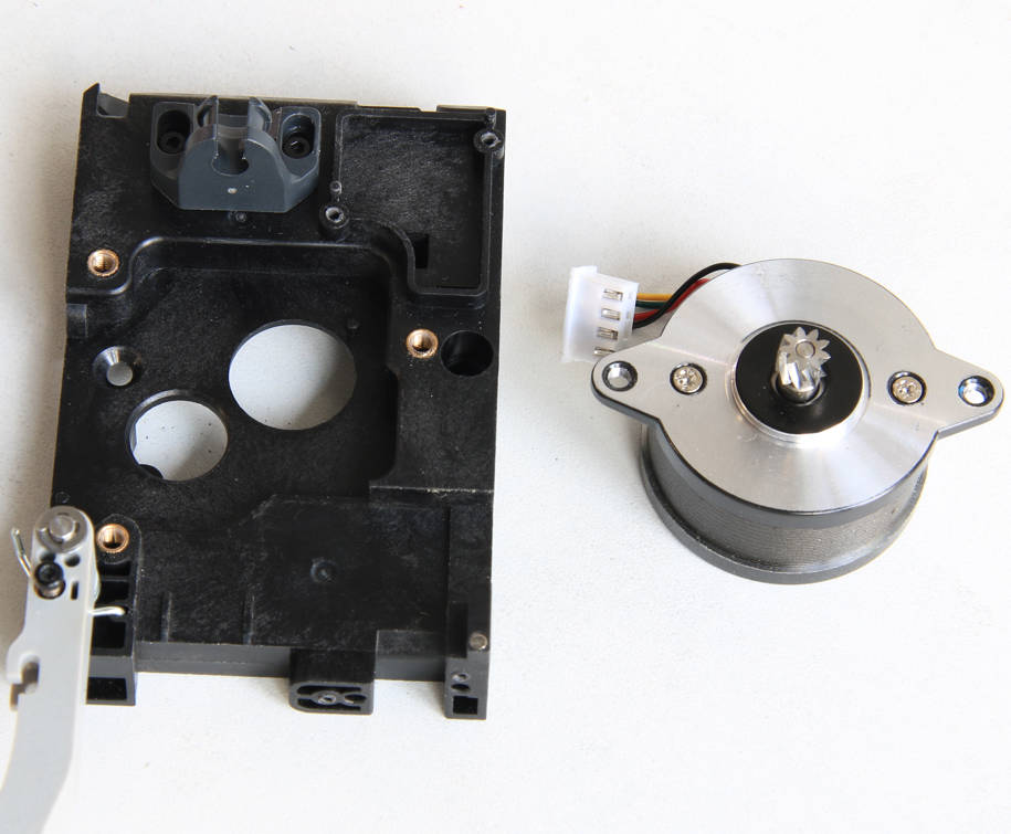
Remove 2 screws with an H2.0 hex key and remove the extruder motor.
|
 |
 |
¶ Step 8 - Install the extruder motor
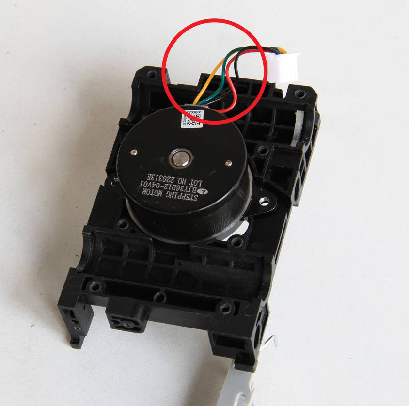
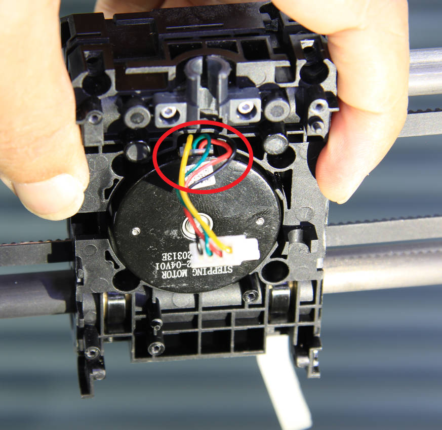
Install the new extruder motor onto the front cover of the slider, ensuring that the motor cable is positioned on top. Then, secure the motor in place by tightening 2 screws.
 |
 |
¶ Step 9 - Install the extruder
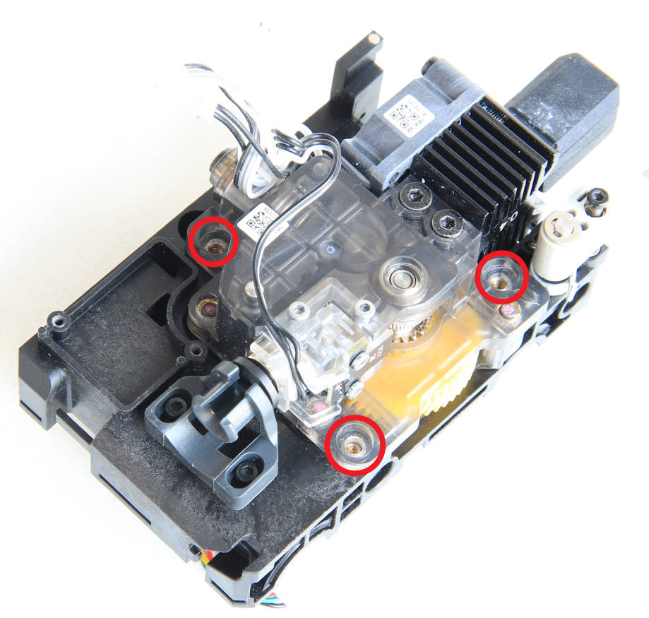
Install the extruder and the hot end together on the front cover of the slider, and then secure it with 3 screws.
¶ Step 10 - Install the front cover assembly of the toolhead
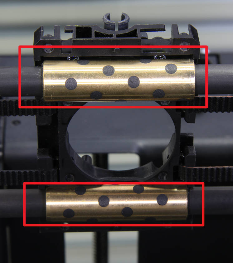
Before installation, ensure that the springs are correctly positioned and that both copper sleeves are inserted into the corresponding grooves on the back cover of the slider. Then, carefully install the front cover assembly of the slider, being cautious not to press against the motor cable.
|
 |
¶ Step 11- Lock screws (4+4)
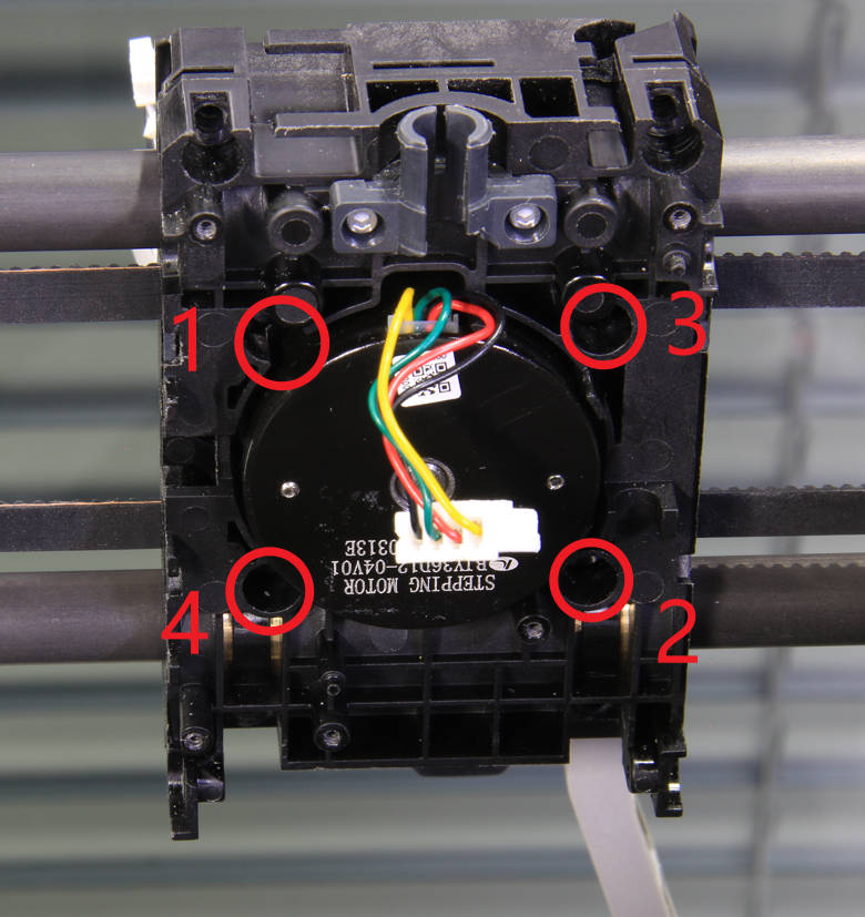
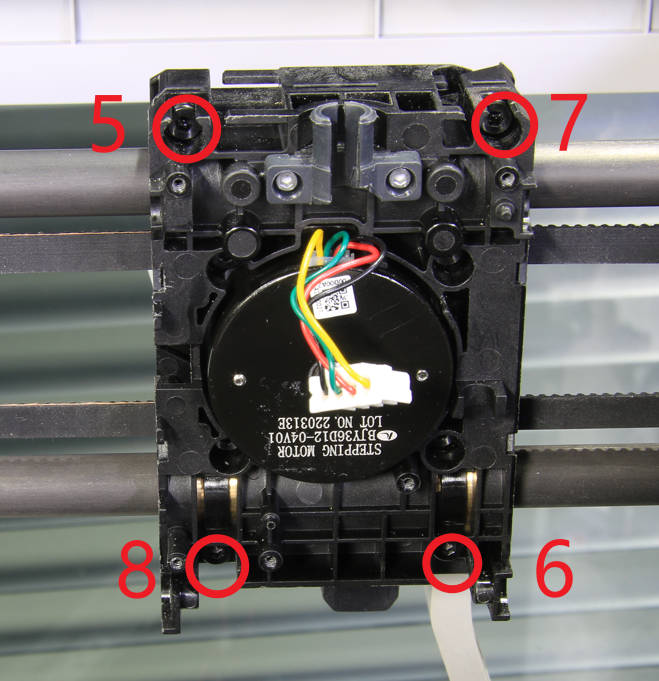
Lock the screws to secure the front cover assembly of the slider. Please tighten the screws in the order of 1~8 as shown in the figure below.
|
 |
¶ Step 12 - Install the bambu micro lidar
Install the bambu micro lidar under the toolhead and secure it with 2 screws.

|
 |
¶ Step 13 - Install the LED cable
Install the tool head system LED light cable.
|
 |
 |
¶ Step 14 - Install the TH board assembly, assemble the toolhead
Refer to the video on Replace the TH board assembly to install the TH board assembly and assemble the toolhead.
¶ To verify completion/success
- Power ON the printer.
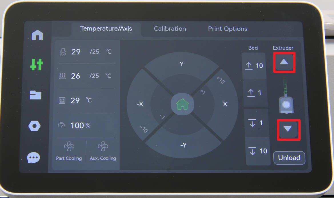
- Click on the extruder button on the screen to verify that the motor can drive the extruder as expected.
- Run a self-test and ensure that there are no error messages associated with the toolhead.
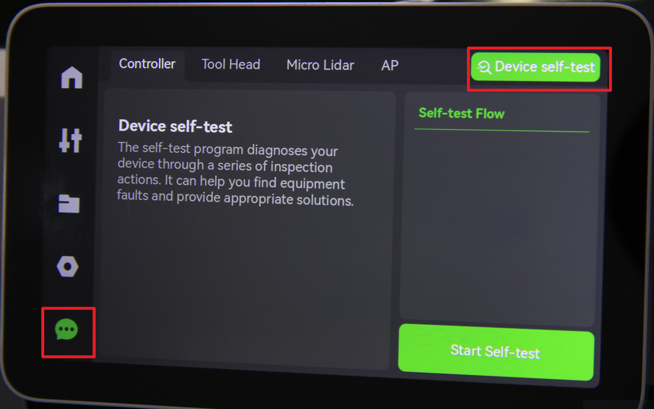
Otherwise, check the connections and try again. If you still encounter errors, contact the technical support team for further assistance.