¶ What is the heatbed signal cable
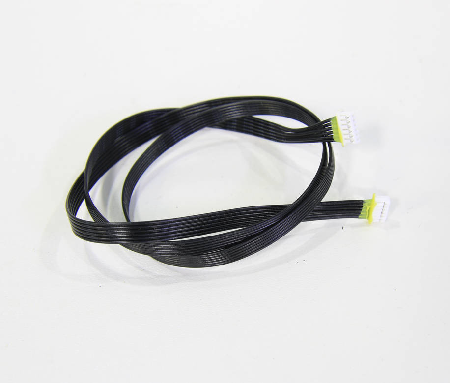
The heatbed signal cable is a 6pin cable connecting the heatbed and the MC board.
¶ When to use
1. The temperature of the heat bed is abnormal, and it has been checked to confirm that the connectors are normal;
2. The temperature of the heat bed is lost during the heat bed movement or printing;
3. Visible damage on the cable or the connector;
4. After the confirmation of the after-sales team, the signal cable needs to be replaced.
¶ Tools and materials needed
- New heatbed signal cable (6pin)
- H1.5/H2.0 hex key
- Tweezers
- Hair dryer
- 3 Z-axis slider fixing screws (if reserved after unpacking)
- Some necessary tape and glue
![]()
Silicone glue, only for reference
¶ Safety warning and Machine state before starting operation
Prior to commencing with the process in this guide, please make sure the machine is switched off.
¶ Operation guide
¶ Step 1 - Adjust the heatbed position
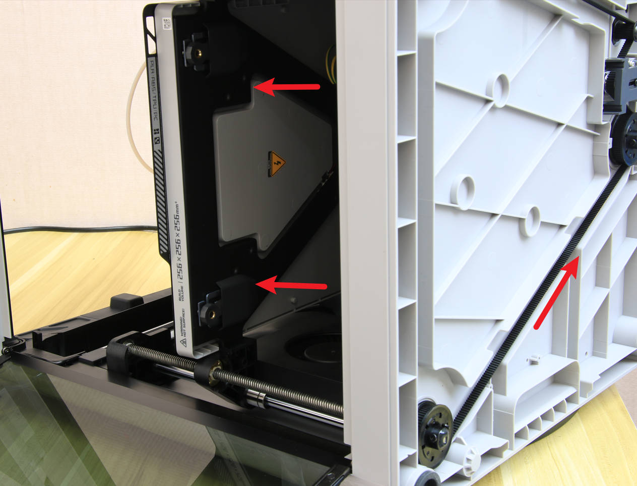
In the startup state, control the movement of the heatbed through the display screen, and place the heatbed at a height of about 2/3 of the way up. Then turn off the printer, disconnect the power cord, and remove the glass top cover. You can also place the printer on its side while it is turned off, and then pull the Z-axis belt to raise the heatbed to a height of about 2/3 of the way up.
¶ Step 2 - Remove the rear cover screws
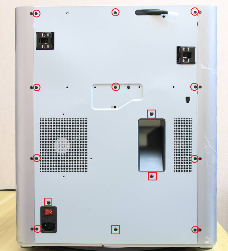
NOTE: There are a lot of screws involved in this procedure. Please label them and group them in separate sections to avoid issues.
Remove the 10 screws and 4 screws from the rear cover shown in the picture. There are 2 types of screws, so keep them separate and remember which ones go where.
¶ Step 3 - Remove the rear panel
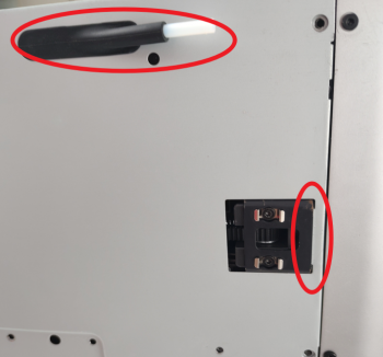
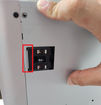
To remove the rear cover, it is important to first pull the right side so that the right belt tension port doesn't get in the way, followed by the right side. Push the PTFE tube outlet inward to free it from the cover.
 |
 |
|---|
¶ Step 4 - Remove the excess chute
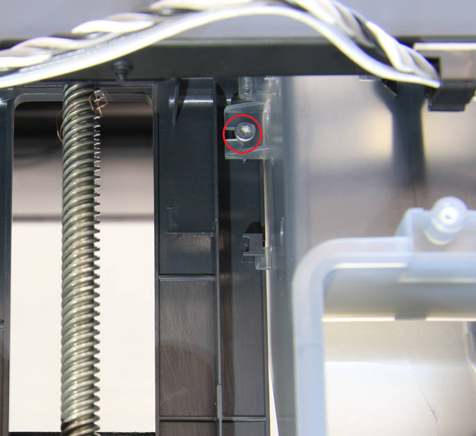
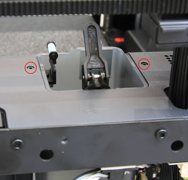
As shown in the figure below, remove 1 silver screw with an H2.0 hex key, remove 2 black screws with an H1.5 hex key, and then remove the excess chute.
 |
 |
|---|
¶ Step 5 - Remove the cable railing
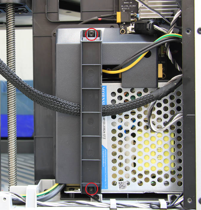
Remove the 2 screws with an H2.0 hex key, and then remove the cable railing
¶ Step 6 - Disconnect the heatbed signal cable
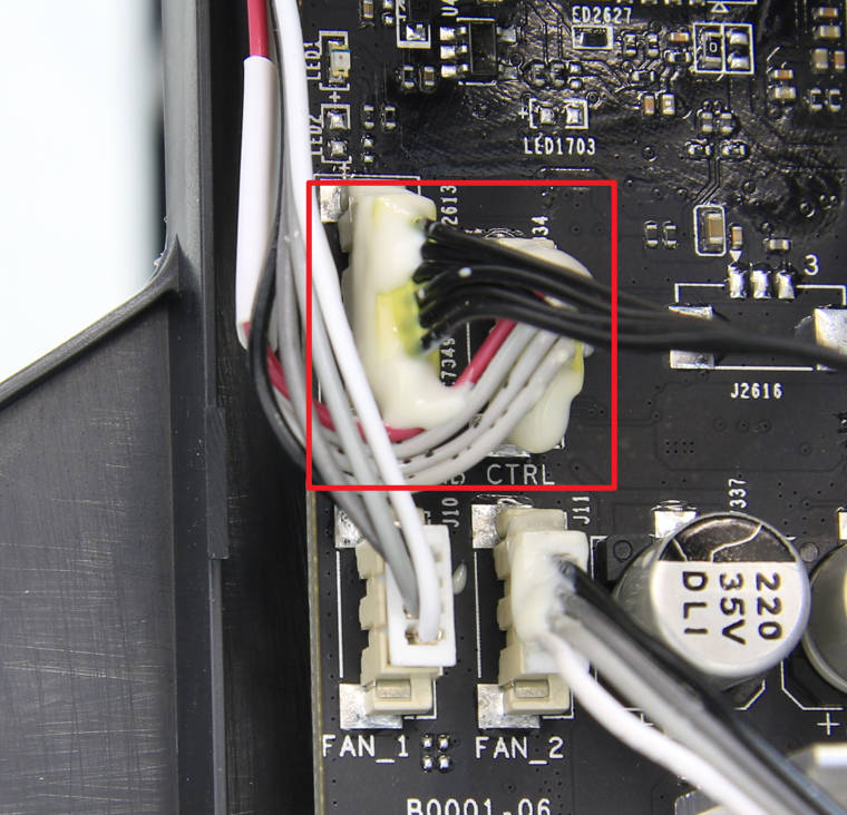
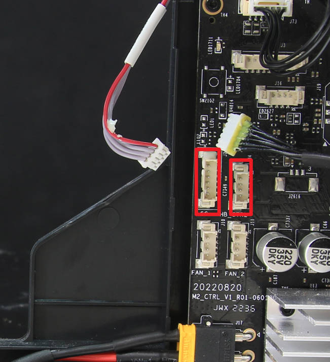
It is recommended to remove some silicone glue from the connector (use tweezers or a hair dryer to heat it, but do not use a heat gun), and then disconnect the signal cable of the heatbed. If the connecting cables of MC-AC are glued together by silicone, you can disconnect them together.
 |
 |
|---|
¶ Step 7 - Pull out the signal cable from the cable mesh
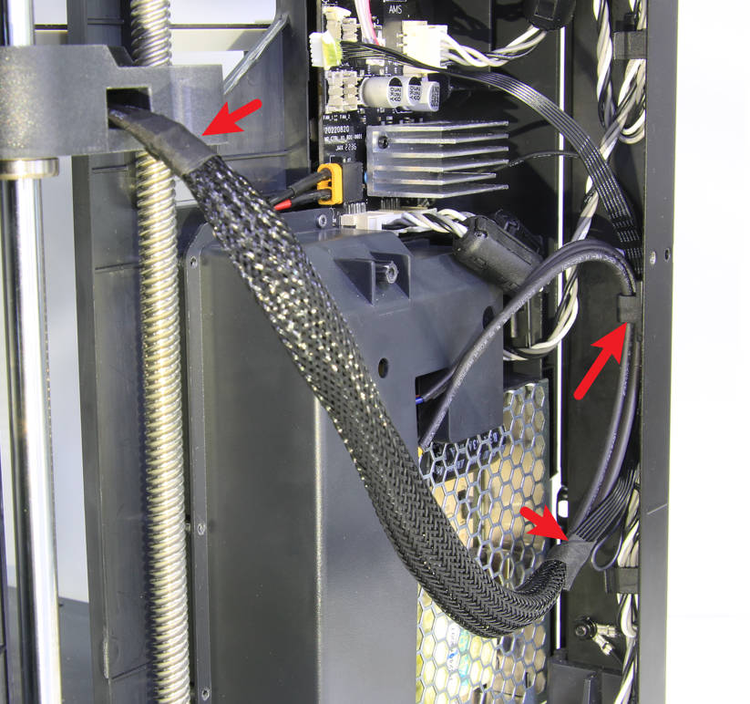
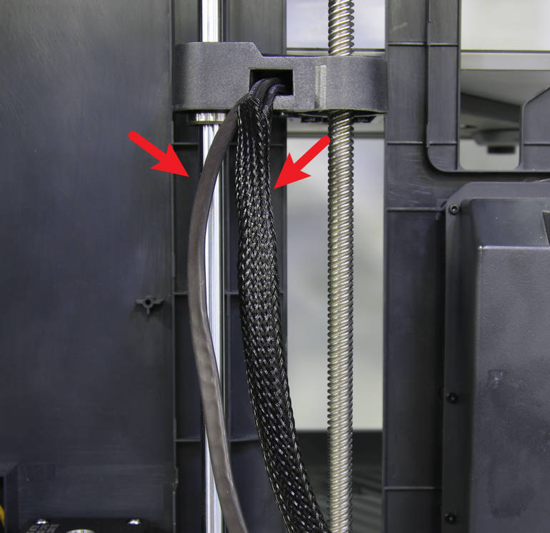
Carefully tear off the tape at both ends of the mesh, and then pull out the signal cable.
 |
 |
|---|
¶ Step 8 - Remove the holding plate
Unscrew 2 screws and remove the holding plate.

¶ Step 9 - Remove the heat bed
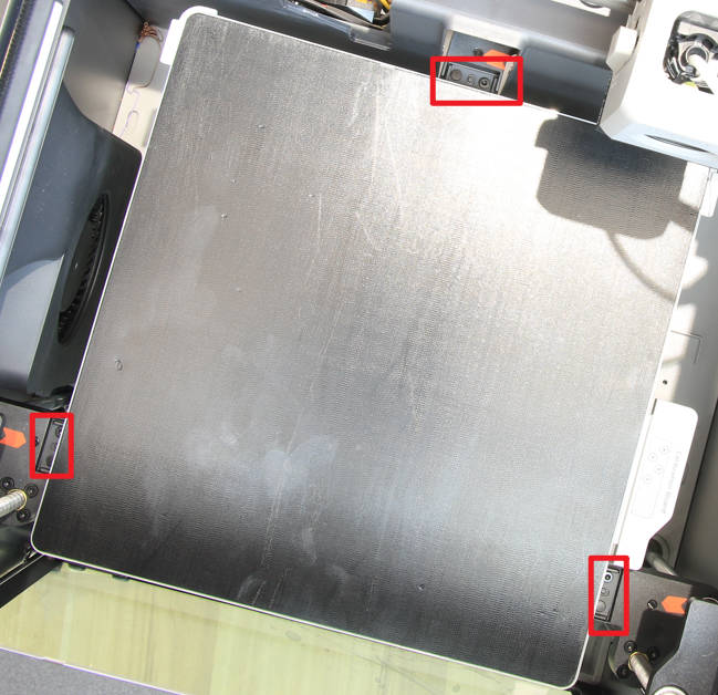
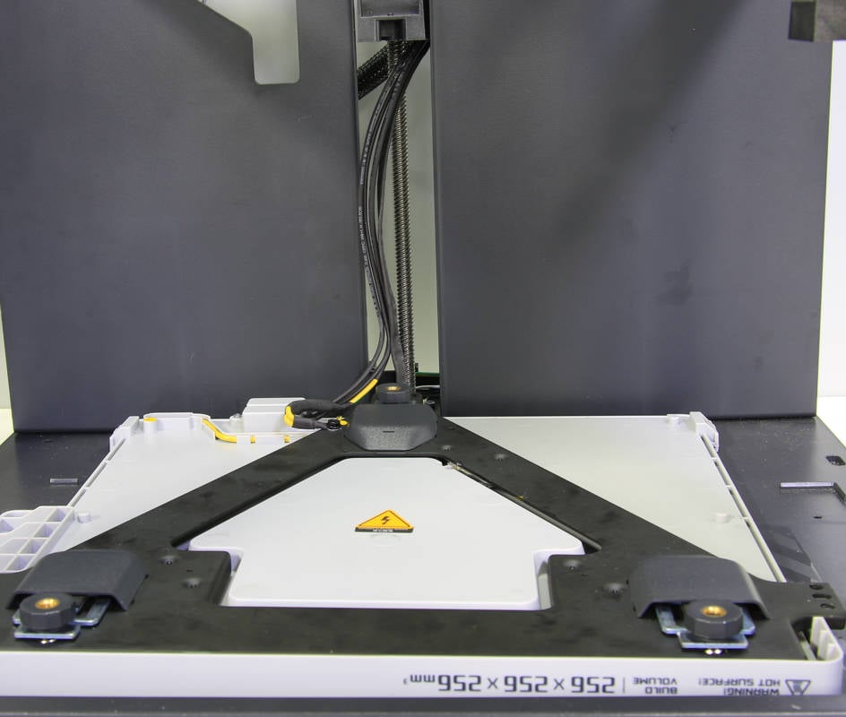
Use the H2.0 hex key to carefully loosen the six screws that hold the heatbed in place and lift it away from the Z-sliders. And then turn it over and place it on the bottom base.
 |
 |
|---|
¶ Step 10 - Remove the leveling nuts
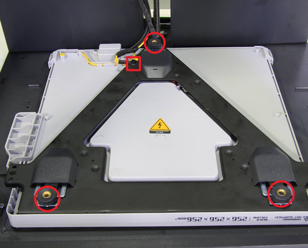
Remove the 3 leveling nuts and rubbers, and remove the ground cable fixing screw.
¶ Step 11 - Open the heat bed bracket
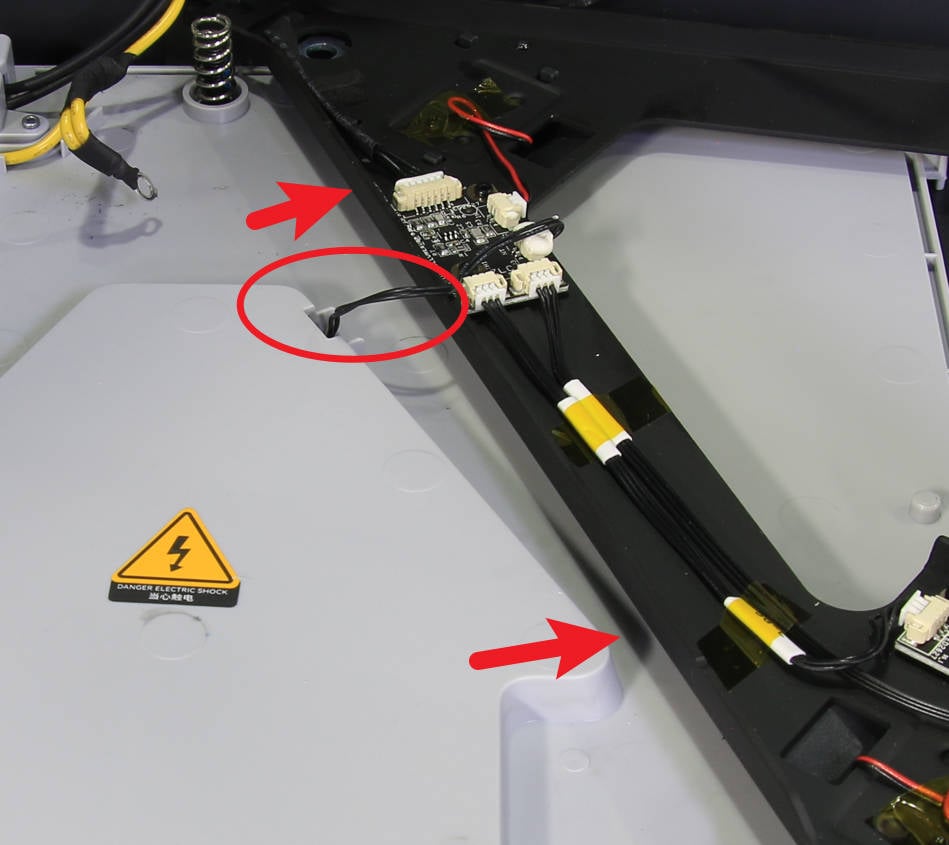
Flip from left to right to open the heat bed bracket, note that there is a 2PIN cable connecting on the board, do not damage it.
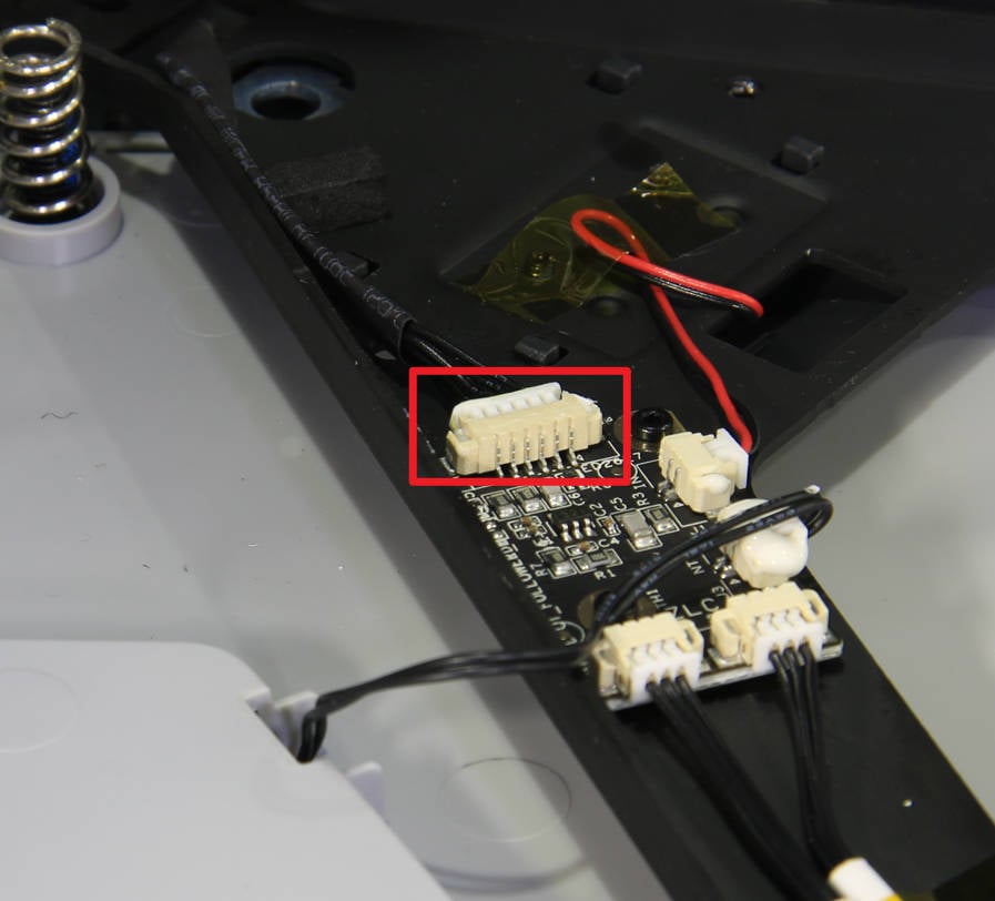
¶ Step 12 - Remove the heat bed signal cable
Clean the silicone glue on the heatbed signal cable connector, disconnect it, and then remove the heatbed signal cable.
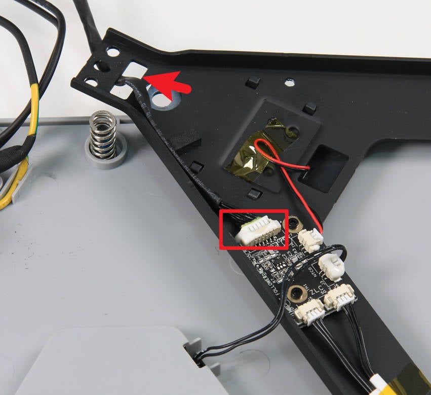
¶ Step 13 - Connect the heat bed signal cable
Pass the heatbed signal cable through the cable hole on the heat bed bracket, connect to the connector on the board, and reinforce it with silicone glue.
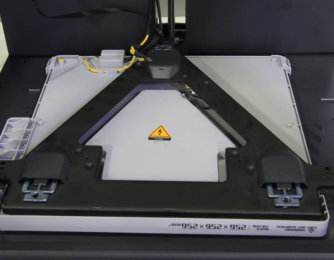
¶ Step 14 - Set the heat bed bracket
Set the heatbed bracket and adjust the position.
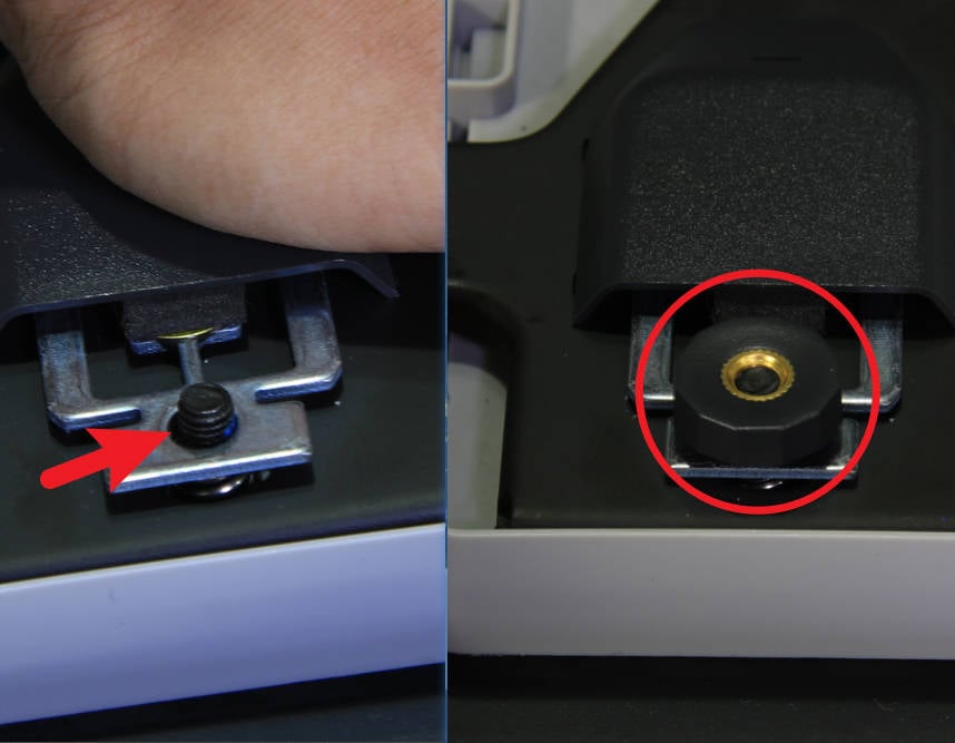
Step 15 - Install leveling nuts
Press the heatbed bracket to to expose the studs, screw in the 3 leveling nuts one by one, trying to screw them in the same height, and then lock the ground cable.
 |
 |
|---|
¶ Step 16 - Installing the heatbed
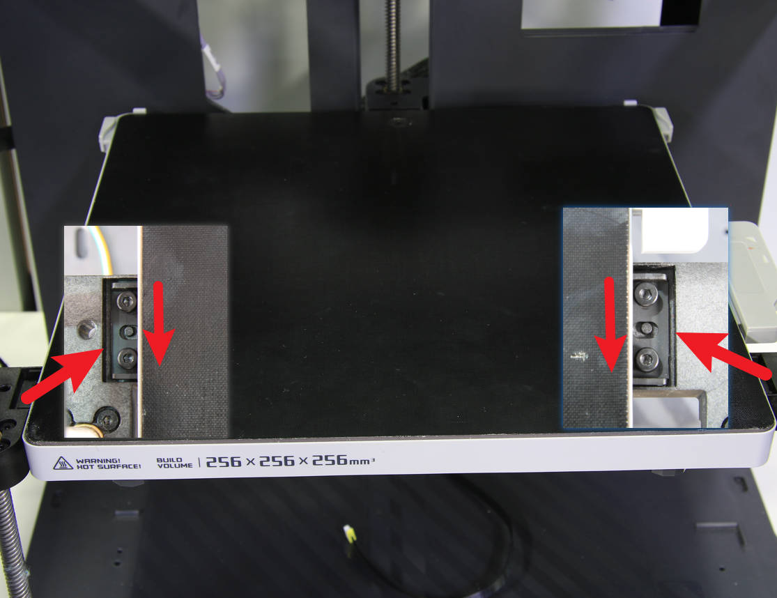
Install the heatbed on the 3 Z-sliders, move the heatbed as far forward as possible, and lock in the 6 screws.
 |
 |
|---|
¶ Step 17 - Pass through the heatbed cables and lock the holding plate
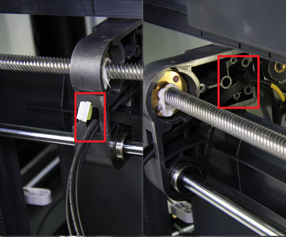
Put the printer on its right side, pass the heatbed signal cable through the cable hole on the rear slider, arrange the cables and press them into the cable groove of the rear slider. Then, install the cable holding plate and lock in the 2 screws.
 |
 |
|---|
¶ Step 18 - Secure the cable mesh
Put the printer upright, pass the heatbed signal cable through the cable mesh, then wrap tapes on both ends of the mesh to fix it, and place the cables to the cable buckle that attached on the column.
¶ Step 19 - Connect the signal cable to MC board
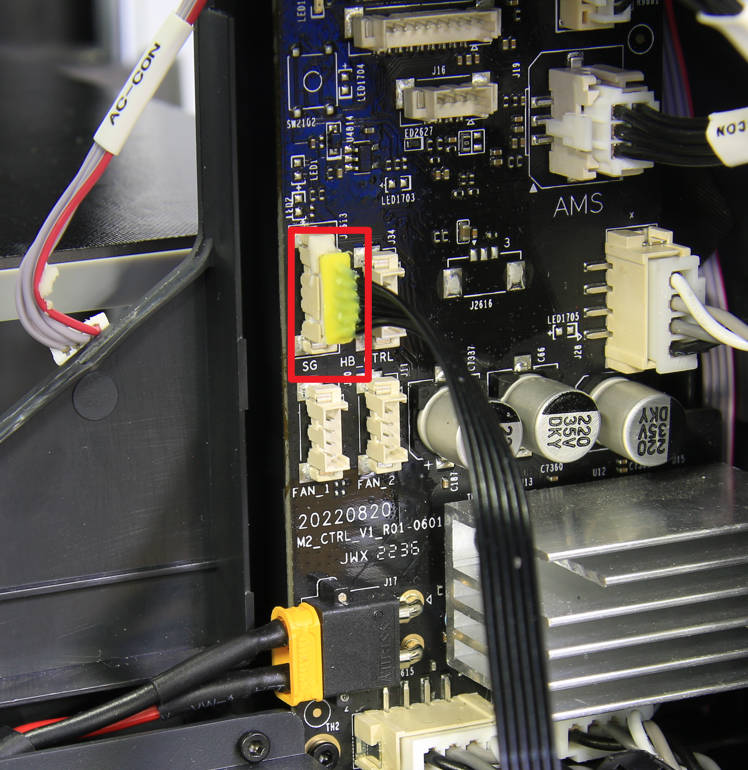
Connect the heatbed signal cable to the corresponding connector on the MC board, enhance the connector with silicone glue, and then connect the MC-AC connection cable.
 |
 |
|---|
¶ Step 20 - Install the cable railing
Install the cable railing to the cable cover and lock in the 2 screws with an H2.0 hex key.

¶ Step 21 - Install the excess chute
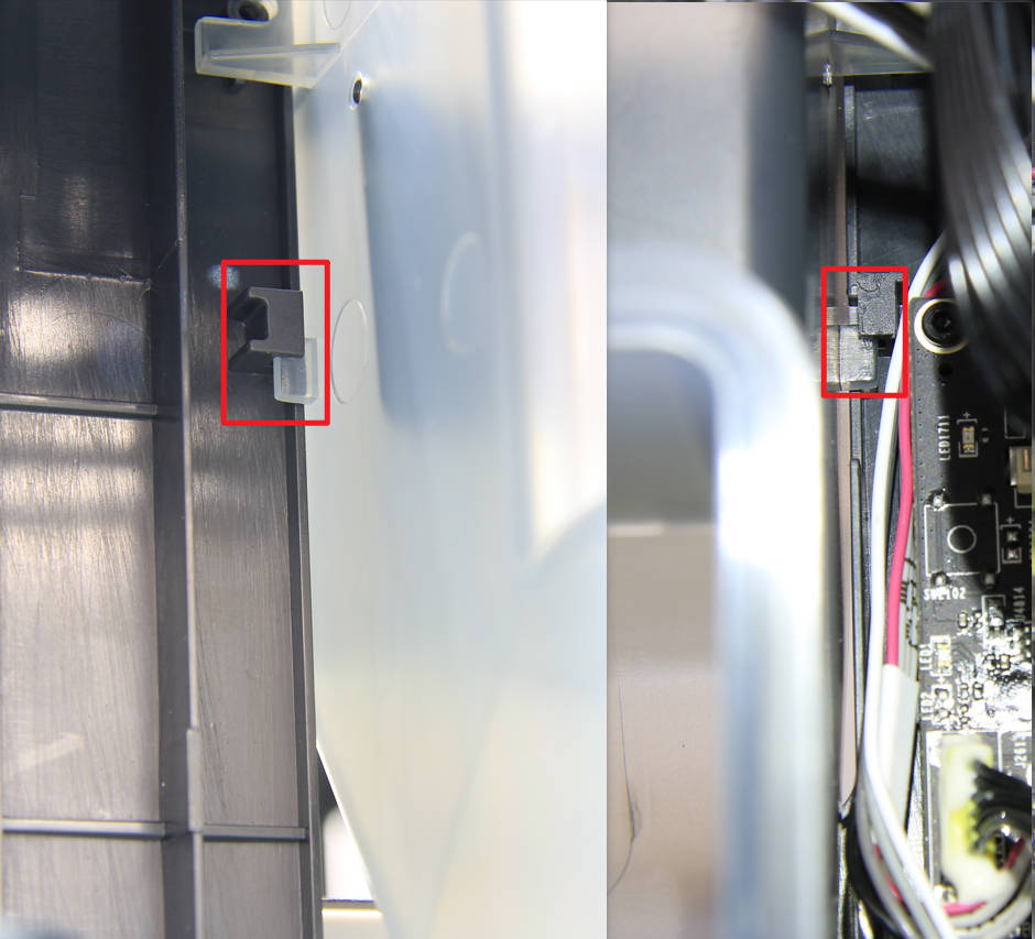
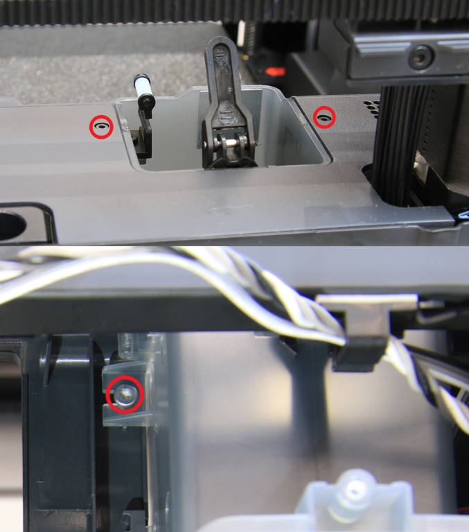
Install the excess chute on the printer, paying attention to the limit buckles on both sides of the chute and install them in place, but do not press the cable.
Lock in 2 black screws on the top of the slide, and lock in 1 silver screw on the left side.
 |
 |
|---|
¶ Step 22- Install the rear cover
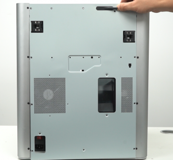
Pass the PTFE tube through the tube bracket. Next, install first the right side belt tension port and then the left side to install the rear cover.
 |
 |
|---|
¶ Step 23- Install the 10+4 screws
Install the 10 + 4 screws (see picture).

¶ How to verify completion/success
Connect the power cord and turn on the power.
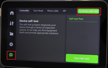
Run a Device self-test operation as shown below, and if no errors occur, the replacement was successful.
Should you come across any issues, first retrace your steps and check all connections to try again. If problems persist, contact the service team for further assistance.