¶ Overview
This article will introduce how the walls of a 3D model are generated during the slicing process. It also explains the differences between, and the advantages and disadvantages of the two wall modes, Classic (constant/fixed line width mode) and Arachne (variable line width mode). This will help users choose one wall mode over another for improved wall quality.
¶ What is the wall generator?
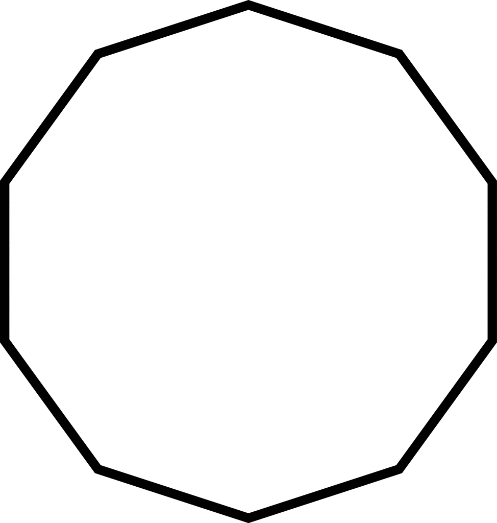
To explain the wall generator, you first need to explain what the “wall” means. A wall is the outline of a two-dimensional shape, the perimeter of a polygon. The black line on the left below is the "wall" of this shape.
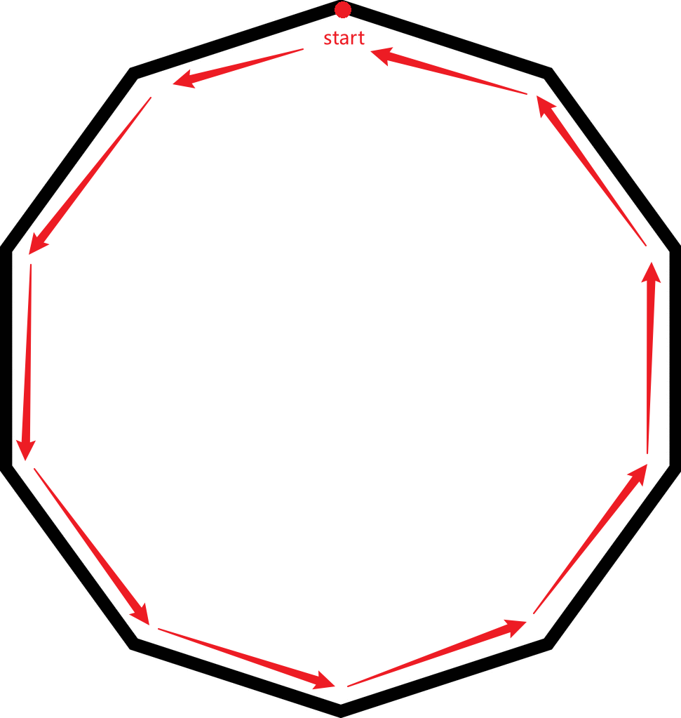
The second is to understand what is a "wall path". The red line in Figure 2 shows how the wall was generated, including its orientation, starting position, and path width.
|
|
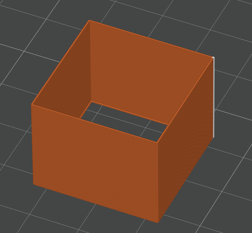
Slicing and printing of 3D models is essentially slicing a 3D model into many layers, and then printing layer by layer into a three-dimensional model. Each of these layers can be viewed as a polygon. The wall generator is responsible for generating wall paths for each layer of polygons. In the 3D view, the shape of the model is shown below.
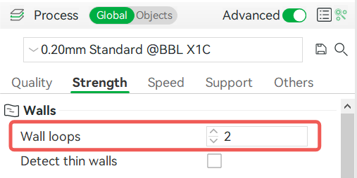
There is also a parameter called "Wall loops" to adjust the number of walls.
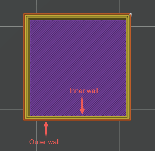
The image below shows a sliced cube model with three walls. The orange path and the yellow path are both the walls of the cube. The outermost wall is called the outer wall, and the other walls are called the inner wall.
¶ How to Select the Wall Generator
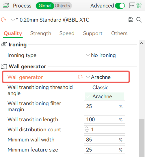
You can select Wall Generator in Process - Quality, which comes in two types: Classic and Arachne. These two kinds of walls use different algorithms to generate the path of the wall, and each has advantages and disadvantages.
¶ How Classic Mode Works
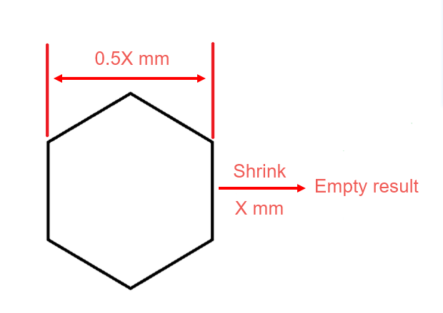
Firstly, it is necessary to explain the meaning of "Shrink" for further explanation. The shrinkage function is shown in the following figure, where the gray polygon represents the original polygon and the orange polygon represents the shrunken polygon. X is the shrinkage width.
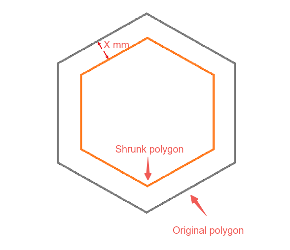
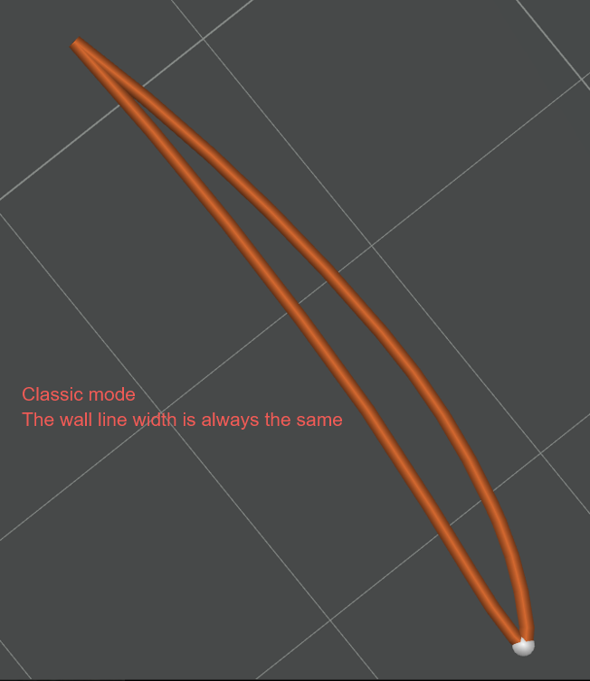
Figure 8 below shows the process of generating a wall path in classic wall mode. The first is the original polygon shape, reducing the set spacing width (half the outer wall line width) to get the first loop path (outer wall). Then, set the spacing width (the center distance between the two walls) for the polygon shrinkage of the first loop walls again. The green polygon in the image below can be regarded as the center line of the generated wall path (that is, the "skeleton" of this loop wall), and the actual path width is the set inner and outer wall linewidth. In classical wall mode, the width of the single path is always the same, and the wall path is always a continuous closed loop.
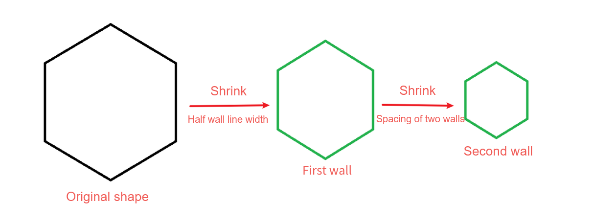
If the polygon is too small, the result of the shrinkage will be empty, so the wall path will not be generated.
¶ Advantages of classic walls
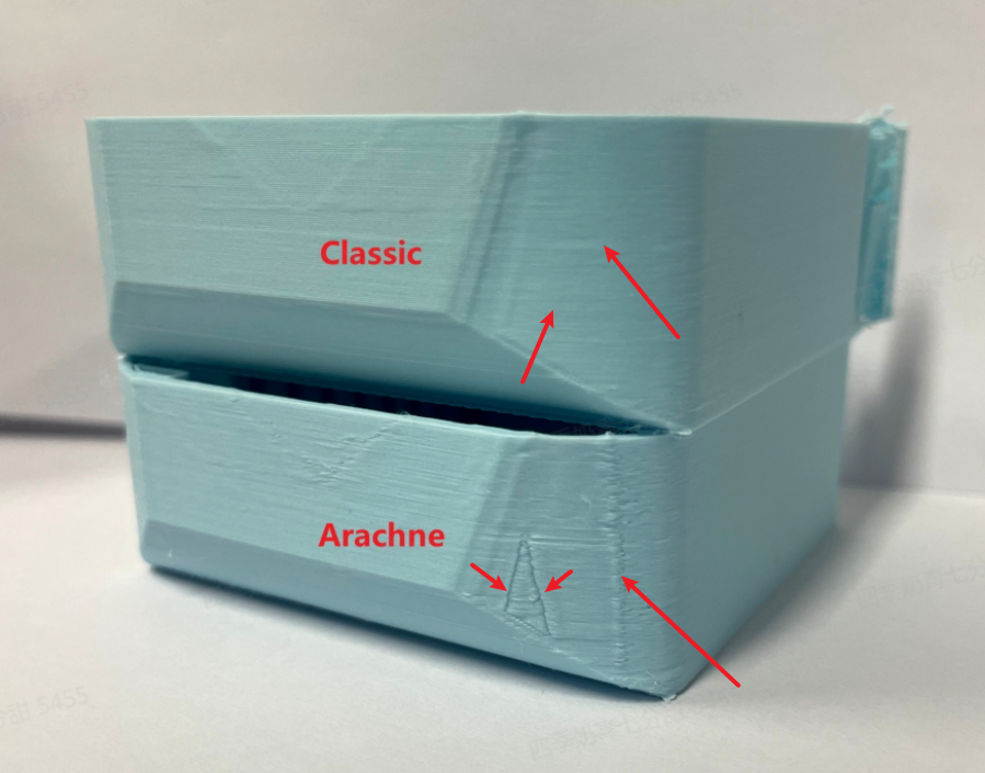
Another concept that needs to be mentioned here is "seams". The "seam" is the gap between the beginning and end of the wall path. It will leave a clear point on the wall and create a clear gap on the surface of the printed model (refer to Seam | Bambu Lab Wiki for details).
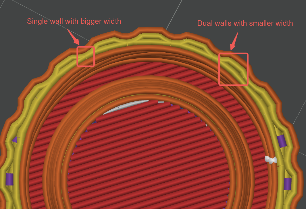
As mentioned earlier, the classic wall path is of uniform width, so the surface quality will be better because it has only one seam per layer. Discontinuous paths may cause multiple seams. Below are the continuous surfaces printed by the Classic wall and the discontinuous surfaces printed by the Arachne wall.
¶ Disadvantages of classic walls
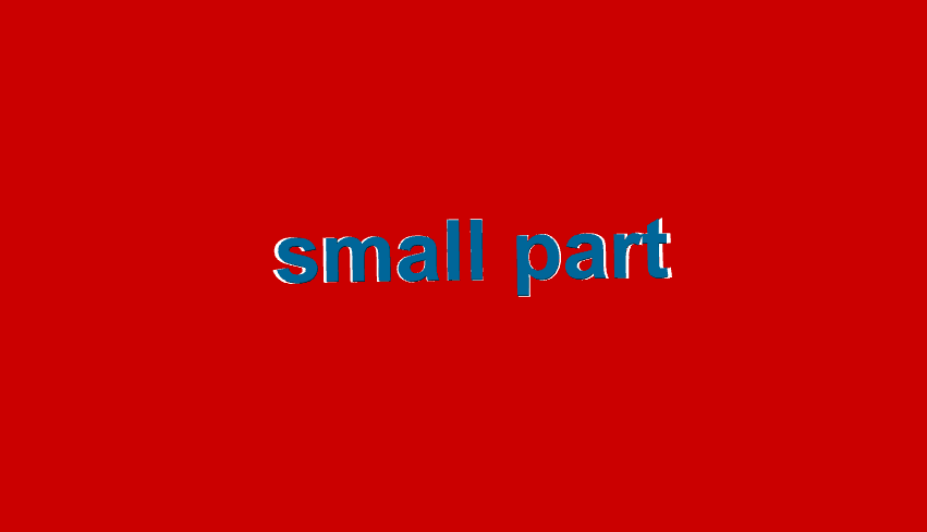
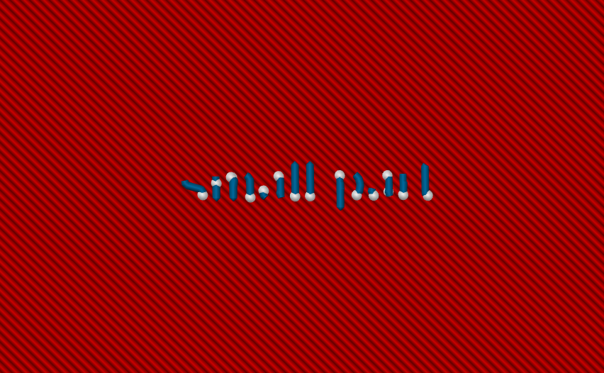
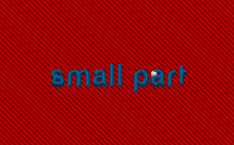
Some models have small parts that are too small to generate a closed wall loop, resulting in missing parts of the model after slicing. For example, the model surface in Figure 11 has very small text, so the wall path of the text cannot be generated after slicing (as shown in Figure 12). Of course, if you change the printer profile to a smaller nozzle size, there is a good chance that it will be successfully sliced. The root cause of this problem is that some parts of the model are too fine, and the required line width is smaller than the default line width of the current size nozzle. Setting a smaller wall width can solve this problem.
¶ Detect thin wall
In some scenarios, the “Detect Thin Wall” feature can solve this problem.
If this option is enabled, the shrink width when the wall is generated is reduced a bit to provide space for the wall path. As shown in the figure below, the spacing between the center of the wall will be smaller when generating thin walls.
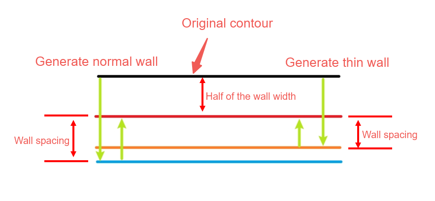
Therefore, when this option is enabled, some details such as small text can also be successfully sliced.
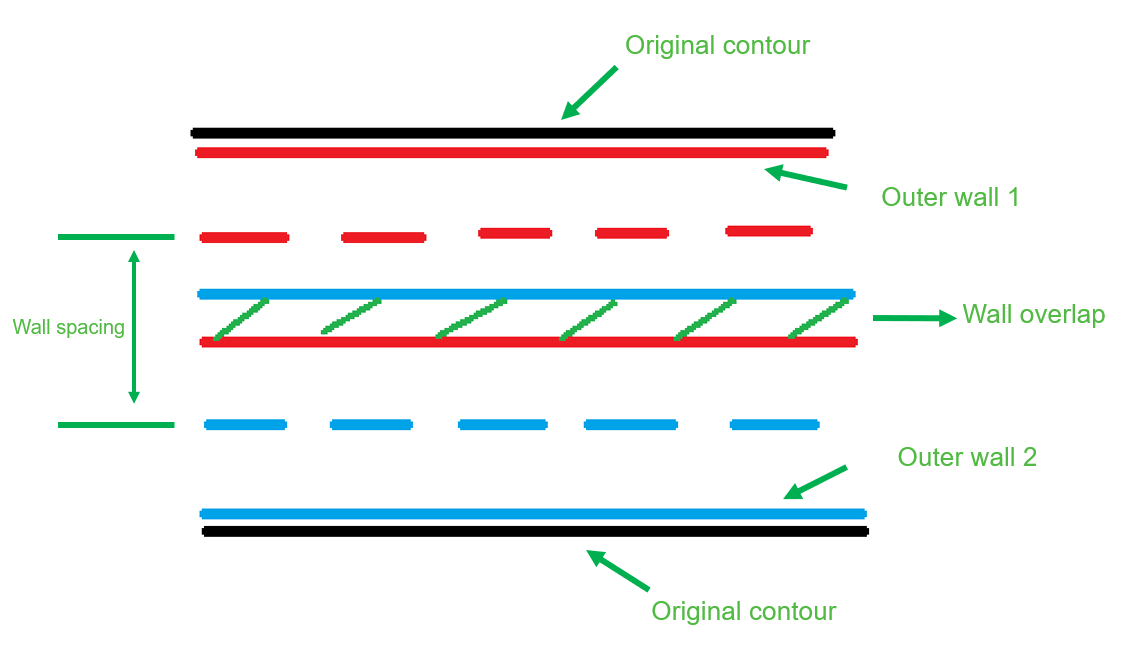
However, "Detect thin wall" can cause other problems in some cases. As mentioned above, because the wall spacing is reduced and cannot accommodate the full line width, there may be overlap between the walls, as shown in the figure below. Black is the original layer shape, red is the outer wall, and blue is the inner wall. The dotted line is the middle line of the wall path, and the solid line is the edge of the wall path. If the spacing of the shrinkage is less than half the width of the wall line, the walls overlap. The excess filament may stick to the nozzle and then stick to other parts during the printing process, resulting in poor surface quality.
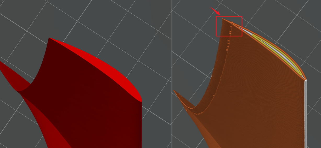
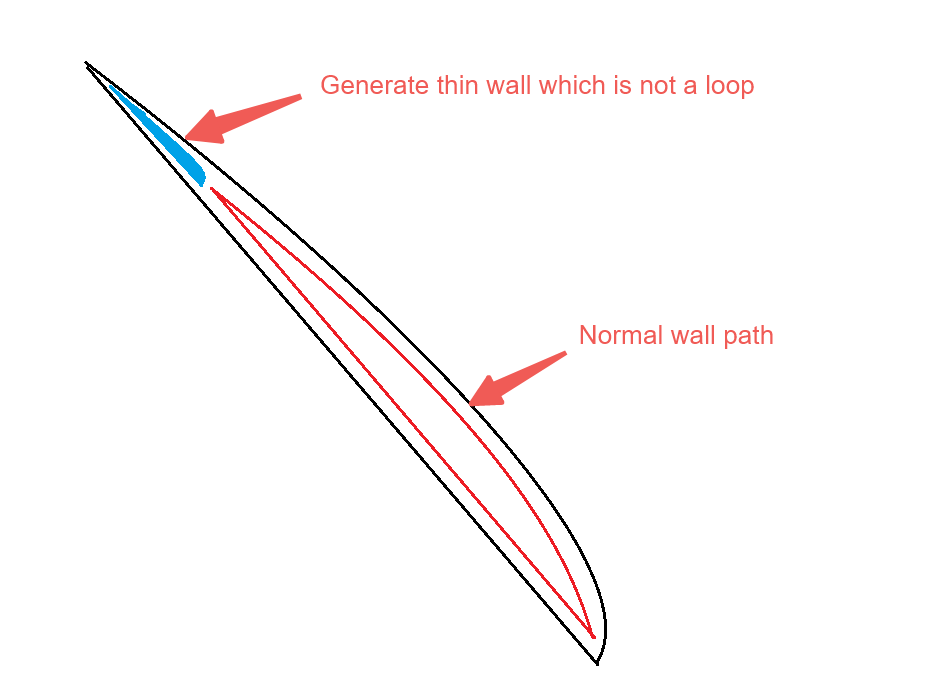
In some cases, some small parts may break off from the original wall line, because the Detect thin wall option also collects small areas to produce thin walls. Some very small sections produce only one wall path line that is no longer closed, as shown in the image below. As a result, the two parts are separate, and thin-walled areas can fail during printing because they are too fragile.
¶ Introduction to Arachne mode
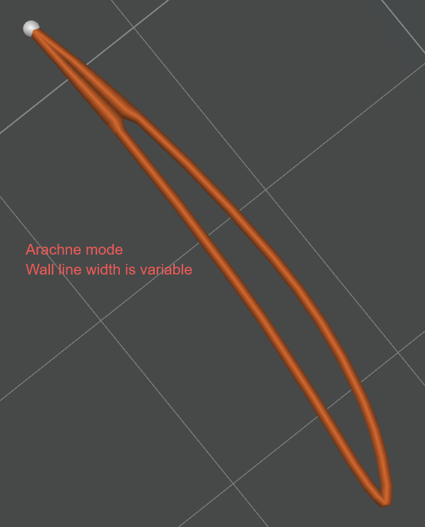
Arachne is also known as the "variable line width mode" because the wall path width is variable. As shown below, a single wall can be generated in different widths. Because the width of the wall can be adjusted, some small details on the model can be generated after slicing, and compared to the "Detect thin wall" function, the wall generated by this mode does not overlap.
¶ How Arachne mode works
The Polygon converts from 2D to 3D, and then it can get the wall paths by the layer cut. If you are interested in it, you can check the article about Framework for Adaptive Width Control of Dense Contour-Parallel Toolpaths in Fused Deposition Modeling - ScienceDirect
¶ Disadvantages of Arachne mode
In some cases, Arachne will generate discontinuous wall paths. For example, some areas cannot generate 2 inner walls of the same width, but a single inner wall of a larger width can be generated (as shown below). Therefore, it is discontinuous with another inner wall. Discontinuous wall paths can affect the print surface quality, as shown in the figure below.
¶ Arachne wall generator parameter Settings
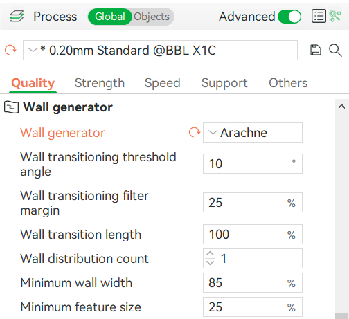
When you select the "Arachne" wall generator, some parameters will appear for adjustment, and the specific explanation is as follows:
¶ Wall Transition
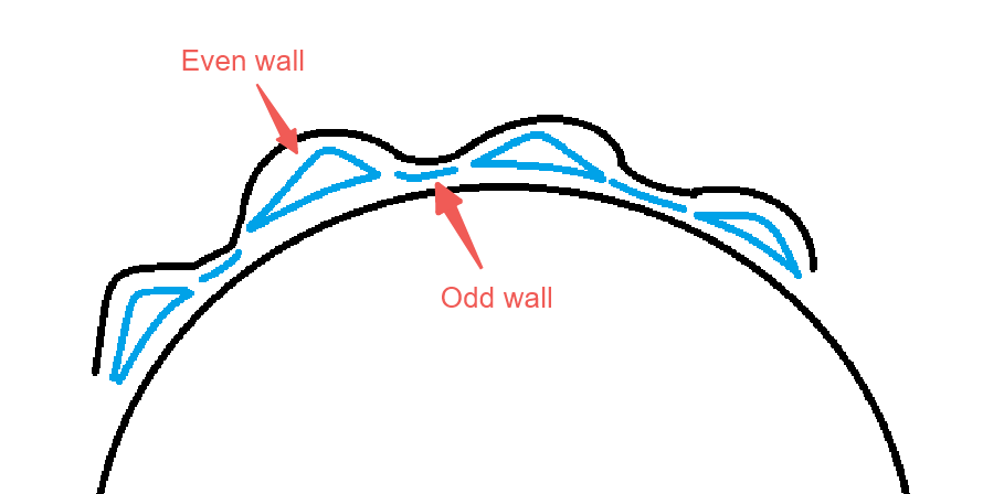
A new concept called "wall transition" needs to be introduced here. First of all, we need to explain the concept of "even wall" and "odd wall": the closed-wall loop is called "even wall", otherwise it is called "odd wall".
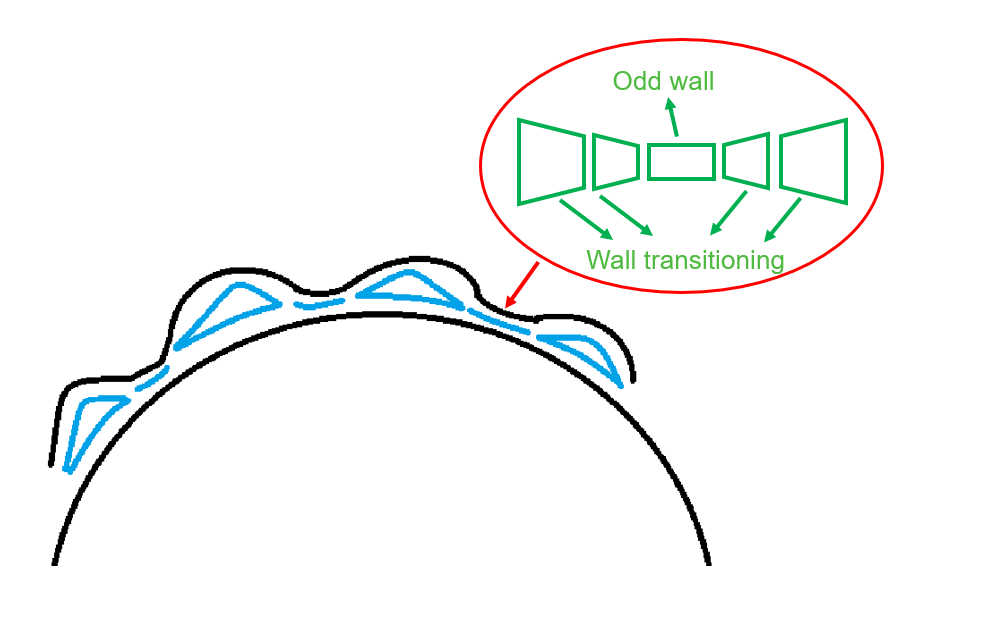
The "wall transitioning" area is a series of wedge-shaped paths that connect even walls and odd walls.
¶ Wall transition threshold Angle
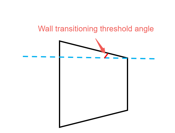
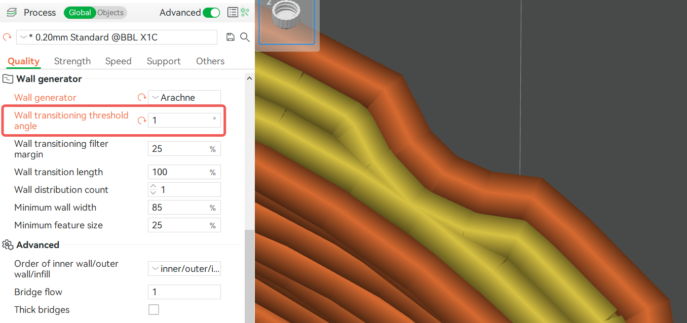
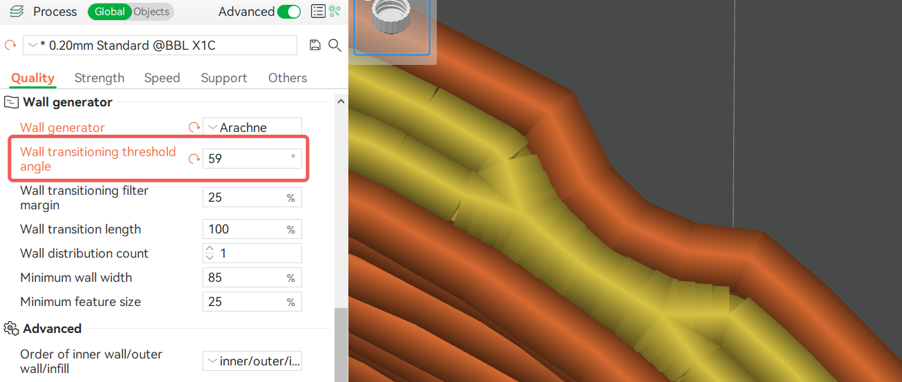
You can see from the figure below what is the threshold Angle of the wall transition. So the wall transition threshold Angle parameter is the maximum threshold for setting that Angle. Increasing this value results in more wedges and shorter wedges, so path transitions are smoother. The value ranges from 1° to 59°.
¶ Wall transitioning filter margin
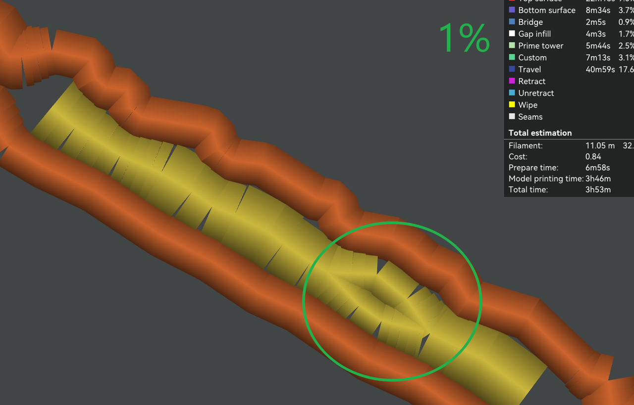
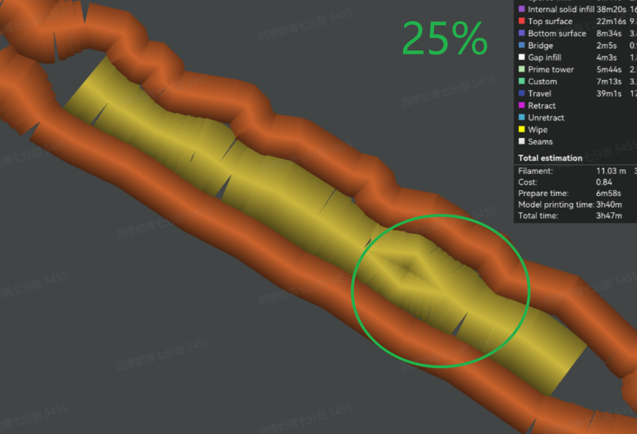
This parameter controls the width range of wall transitioning. The width range is [minimum wall width - margin, 2*minimum wall width+magin]. The parameter value is the percentage relative to the nozzle diameter.
If the width range is extended, the number of wall transitionings may increase to fit the path width. And improve traveling time while some paths get better sequence. However, the increase of wedges may cause over-extrusion, which may damage the surface quality.
¶ Wall transitioning length
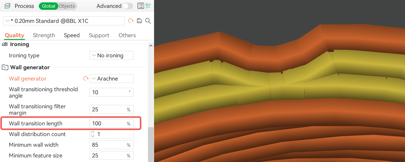
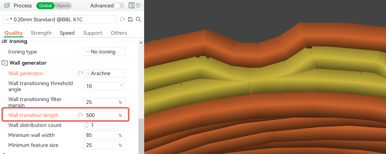
This parameter controls the length of the wall transition, and the parameter value represents a percentage relative to the nozzle diameter.
¶ Wall distribution count
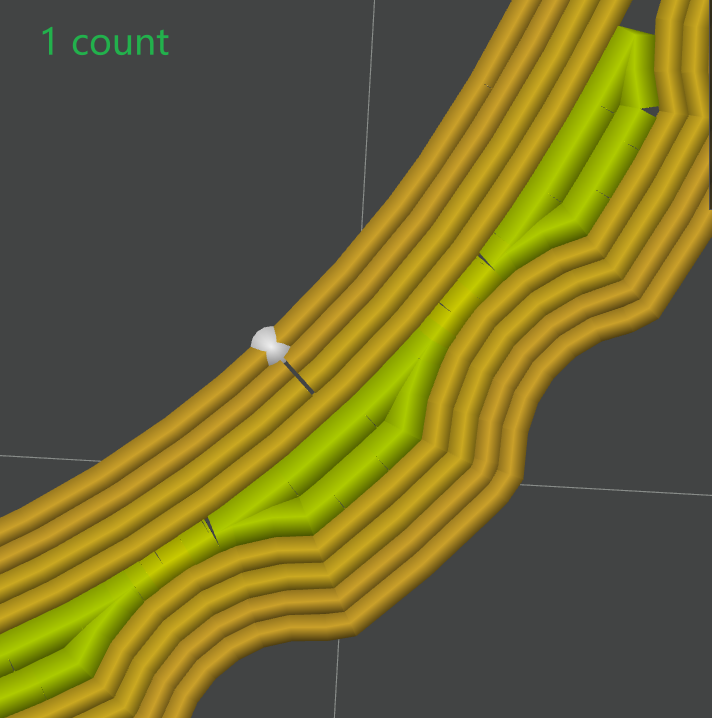
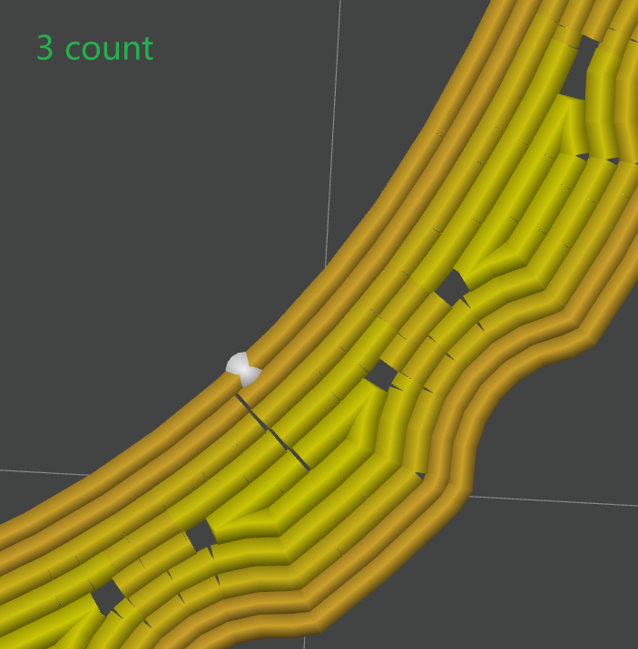
This parameter adjusts the number of walls, counted from the center, whose widths are modified to fill a space. The following Figure shows the different widths and different colors. Figure 32 shows the width of one wall modified to fill the space, and Figure 33 shows the width of 3 walls modified to fill the space.
¶ Minimum wall width
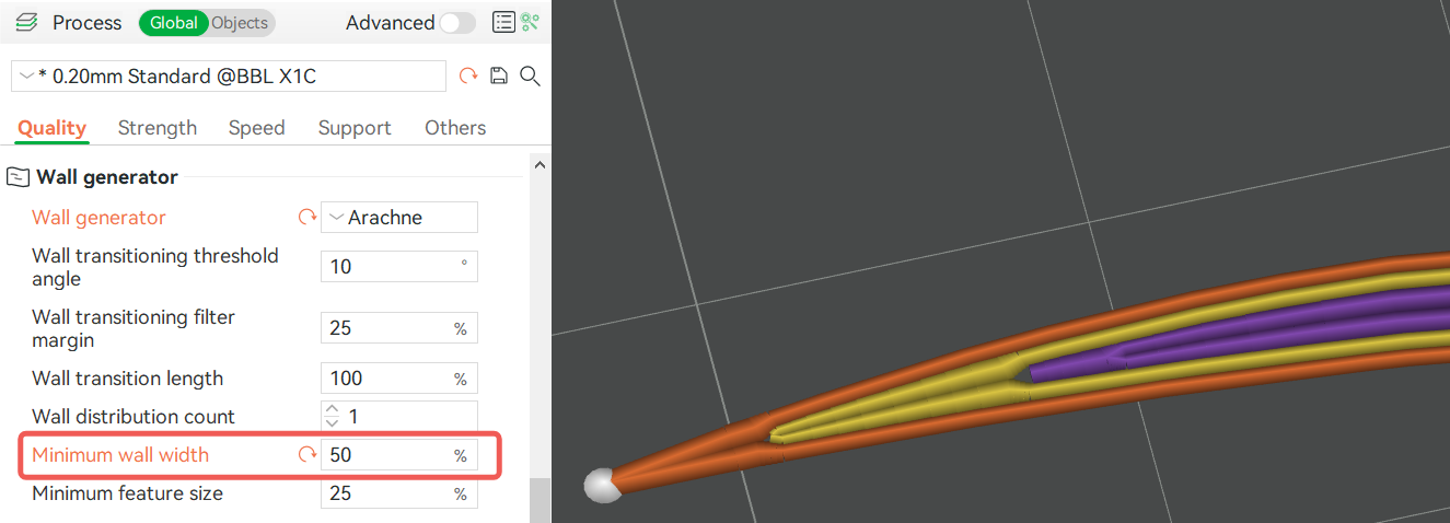
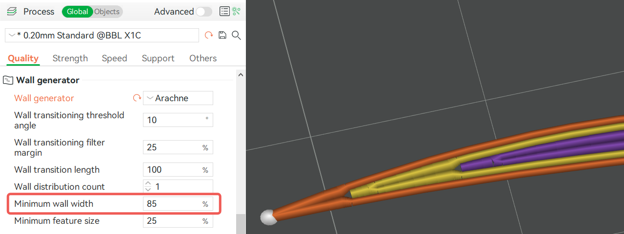
This parameter limits the lower limit of the wall line width. It represents the percentage relative to the nozzle diameter. For example, the 0.4mm nozzle diameter, 85% of the minimum line width of the wall indicates the wall path generated by the variable line width, and the thinnest part is 0.85*0.4=0.34mm.
¶ Minimum feature size
It's a width filter. If the width of a path is less than this threshold, the path is not printed. If the path width is greater than the threshold but less than the minimum wall linewidth, the path width will be automatically extended to the minimum wall linewidth. This parameter represents a percentage of the relative nozzle diameter. For example, if a 0.4mm nozzle configuration is selected and a path width of 0.25mm is greater than 25% (0.1mm) of the nozzle diameter, it will automatically be extended to 85% of the nozzle diameter width, that is, 0.34mm.