¶ What is bridge
Bridge means the line that is completely extruded in the air, it is not supported by the last layer or heat bed, and the overhang degree reaches 100%.
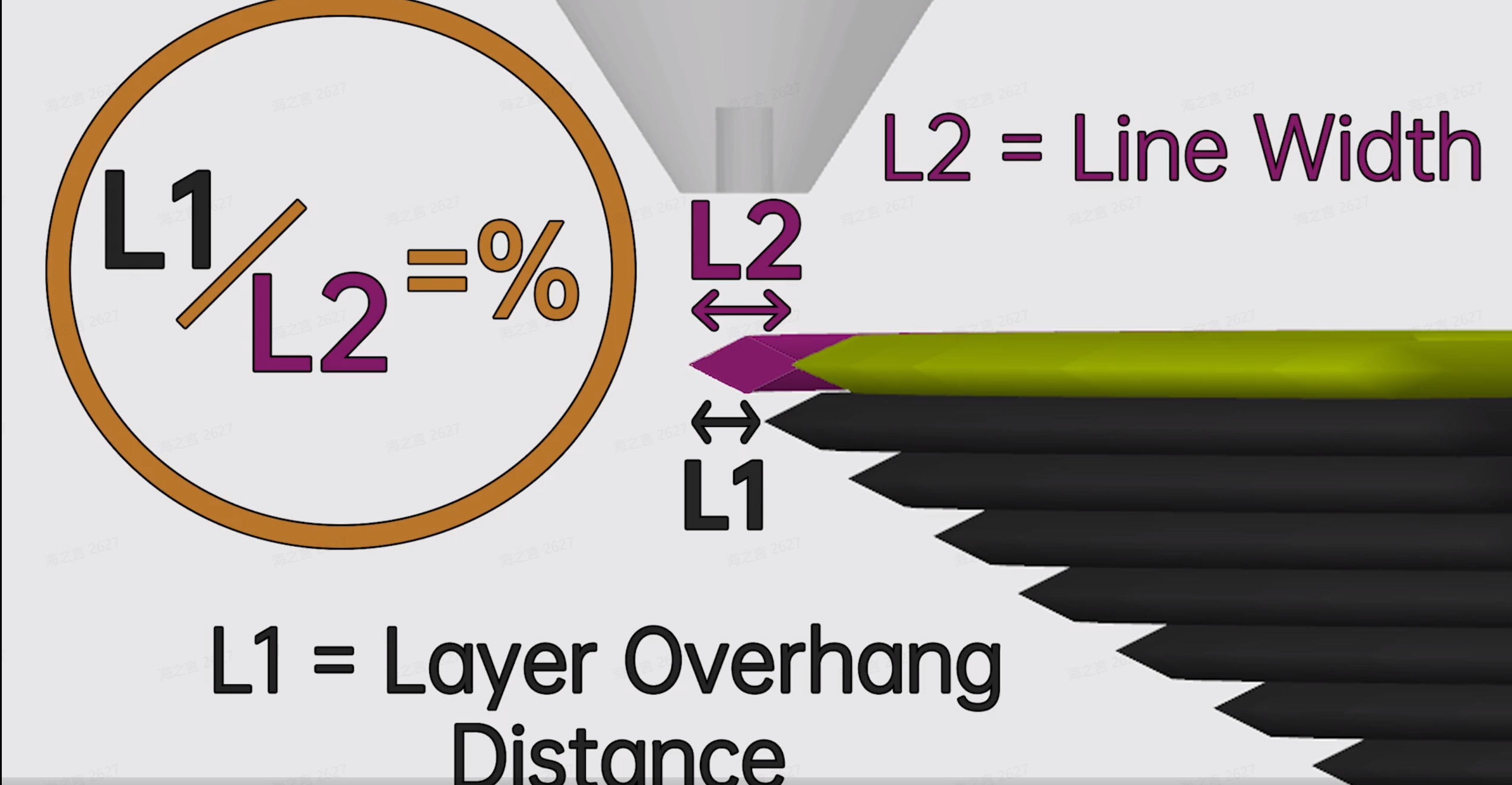
The overhang degree is expressed as a percentage from a microscopic point of view that the width of the filament is not supported by the lower layer. The figure is shown below (L2=line width, L1=overhang width ).
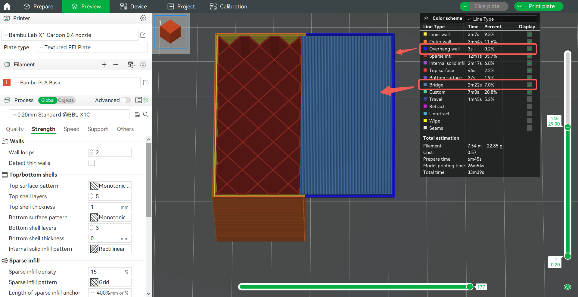
The internal solid infill and bottom surface with 100% overhang degree is defined as the bridge, and the wall with 100% overhang degree is defined as an overhang wall. We can regard the overhang wall as a kind of bridge.
Layer height and line width can only be controlled when extruded on an existing surface, such as a previous layer or heat bed. If it is extruded in the air, the line shape will always be circular. Refer to this wiki for details: Line width | Bambu Lab Wiki。
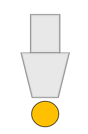
Therefore, we are unable to set the layer height and line width for the bridge. The printer can only control the extrusion flow when printing the bridge. When the bridge first leaves the nozzle, it must be a cylinder with the same diameter as the nozzle. In the air, it may remain as thick as the nozzle diameter, or it may be pulled thinner. The thickest bridge that can be printed from a 0.4mm nozzle will be a 0.4mm cylindrical shape.
¶ Thick bridge and bridge flow
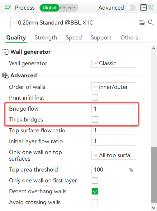
In Bambu Studio, you can set the bridge flow and thick bridge in Process - Quality.
¶ Thick bridge
The thick bridge refers to the extrusion of a bridge line that is equal in diameter to the nozzle. For example, using a 0.4mm nozzle to extrude a 0.4mm diameter bridge, the bridge line is called the thick bridge. This parameter only applies to external bridges, and internal bridges within the model (such as bridges on sparse infill) always have the thick bridge enabled.
When the thick bridge is not enabled, the extrusion flow of the bridge and overhang wall is calculated according to the layer height and line width of the original line type. If the original line type is 0.2mm layer height and 0.4mm line width, when it is an overhang wall or bridge, the flow rate of the bridge is calculated according to the layer height and line width.
Below is a preview example of the different Bridges sliced with the 0.4mm nozzle:
- The internal bridge is always the thick bridge, and the layer height and nozzle diameter in the preview are the same;
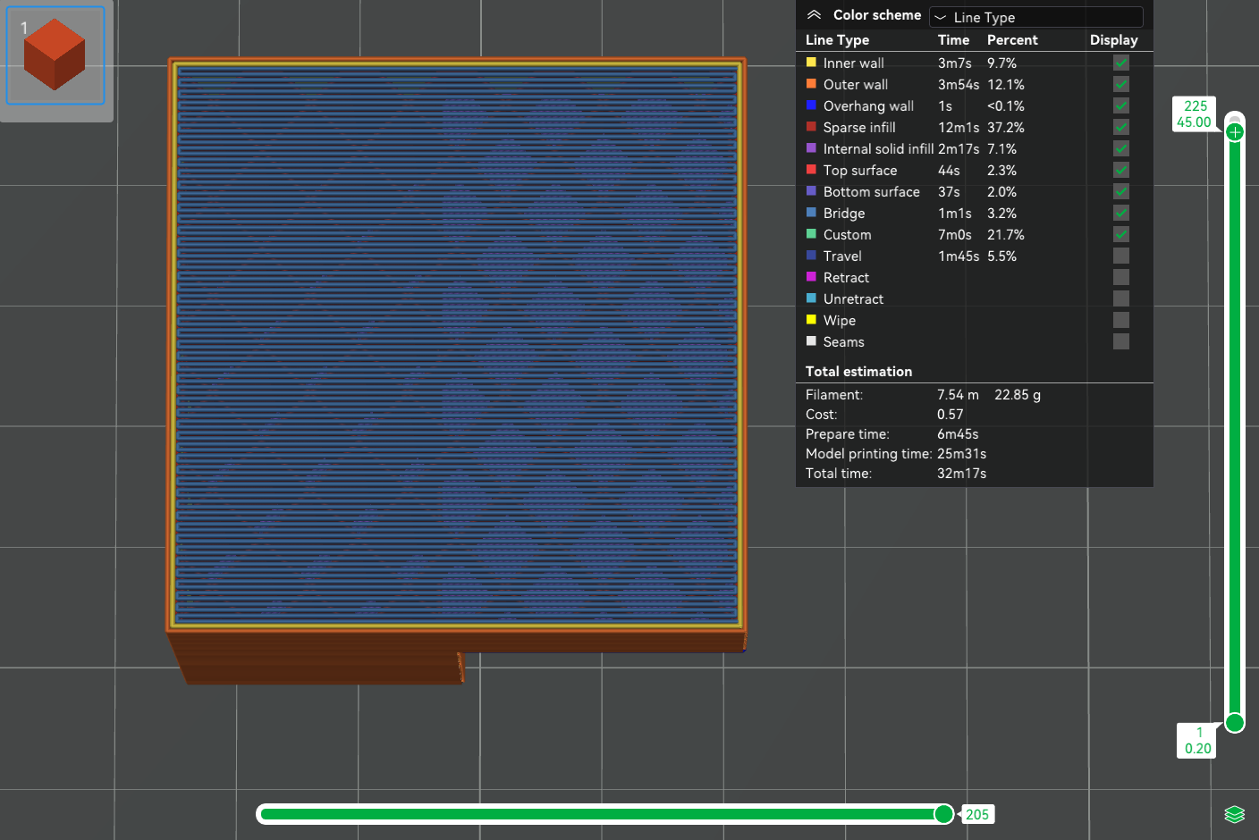
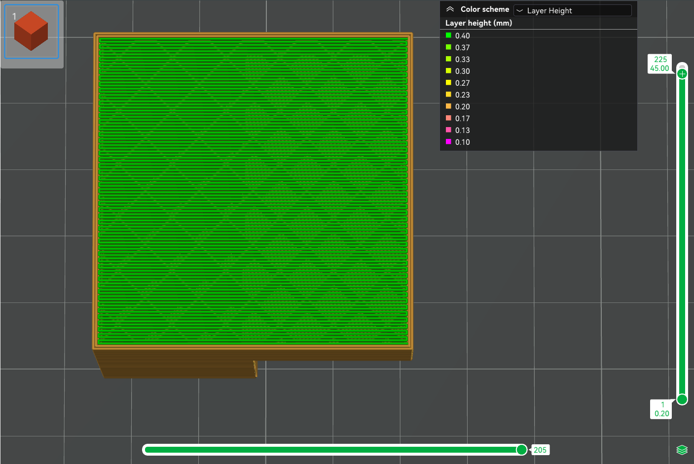
2. External bridge, thick bridge not enabled. The layer height in the preview is still the same as the height set, indicating that the bridge is extruded according to the flow calculated by the layer height and line width of the original line type. At this time, if the original layer height is small, the extruded bridge may be pulled apart due to insufficient material.
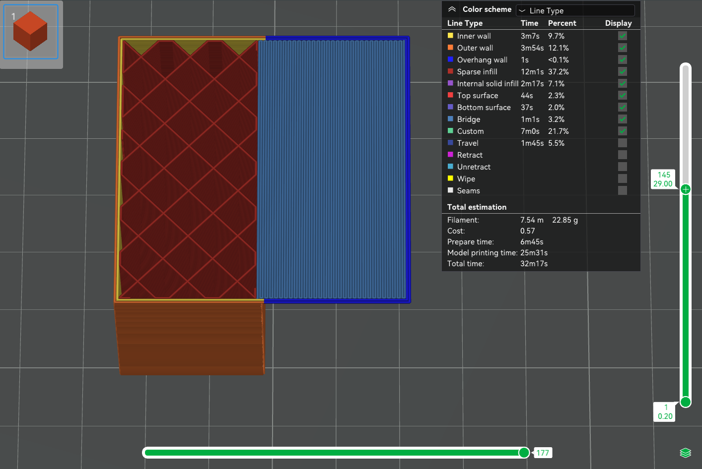
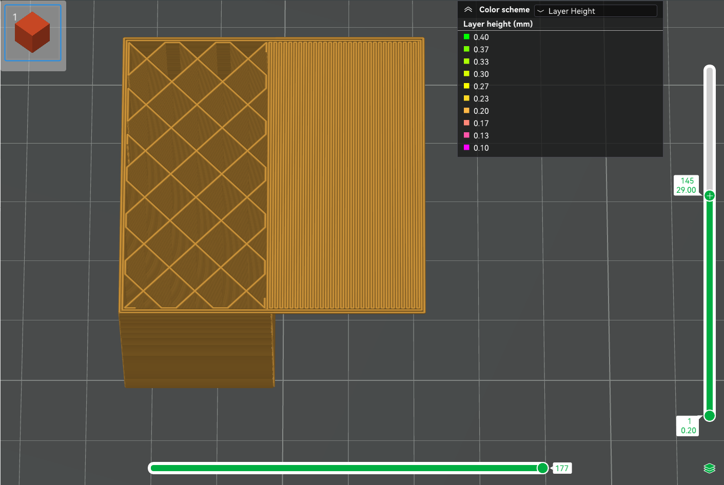
3. External bridge, thick bridge enabled. In the preview, the layer height and nozzle diameter are the same, indicating that the extruded bridge is a cylinder with the same diameter as the nozzle;

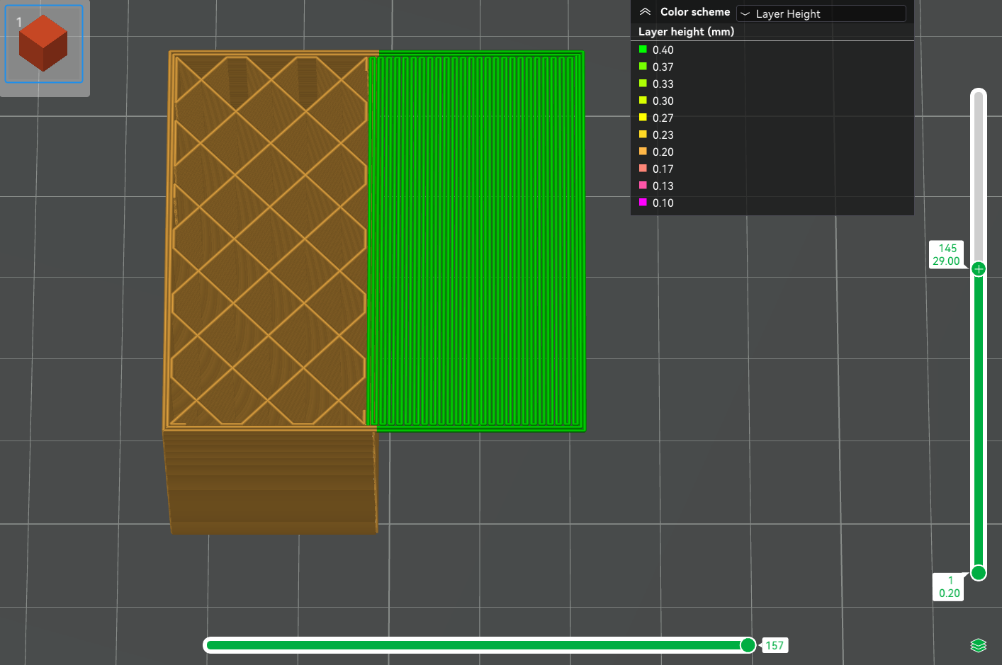
So we can conclude that when the thick bridge is not enabled, the extruded flow rate of the external bridge is calculated according to the layer height and line width of the original line type. After the thick bridge is enabled, the bridge flow is calculated according to the cylinder of the nozzle diameter.
We can also draw the following conclusions:
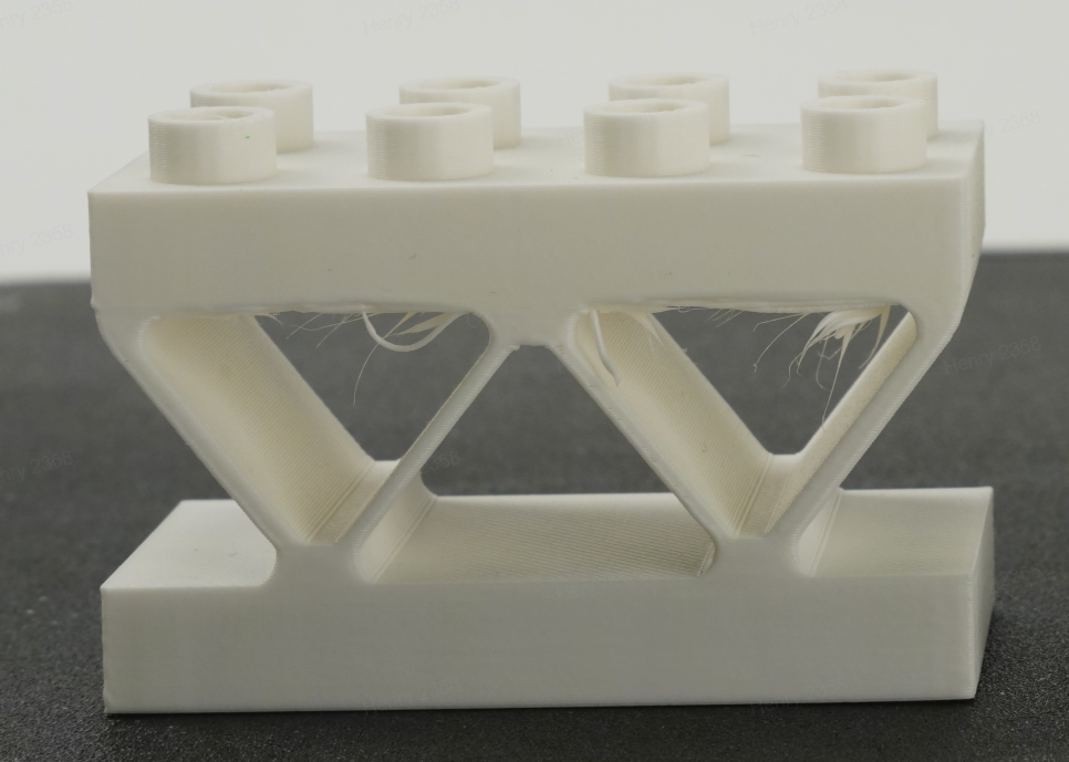
- If the thick bridge is enabled, bridges are more reliable and can bridge longer distances but it may fall.
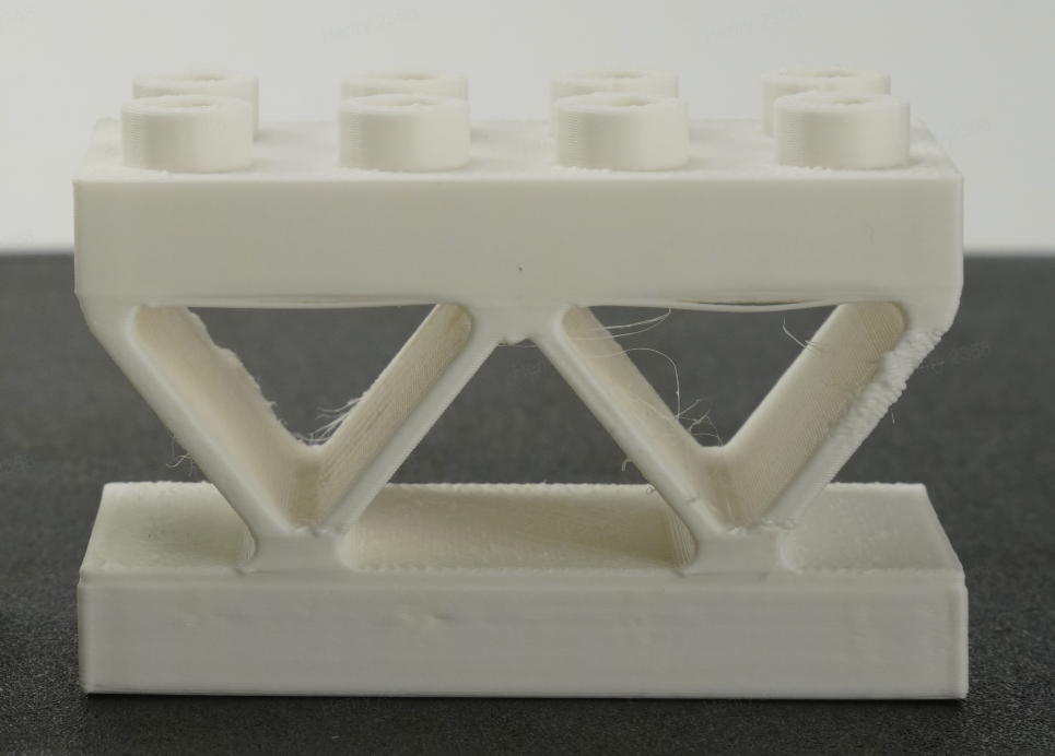
- If the thick bridge is disabled, the bridge looks thin but only works for shorter bridging distances. If the setting layer height is low, the bridge flow may be too small and cause the bridge to break.
¶ Bridge flow
Multiply the original bridged flow by the coefficient set here. If the thick bridge is enabled, the bridge flow of the thick bridge is multiplied by this coefficient. For example, set it to 0.9 to appropriately reduce the amount of bridge material to avoid sagging.
¶ Bridge direction
Set the bridge direction for the external bridge. If set to 0, the Angle will be calculated automatically. Otherwise, the external bridge will use the provided value. 180° indicates 0°.
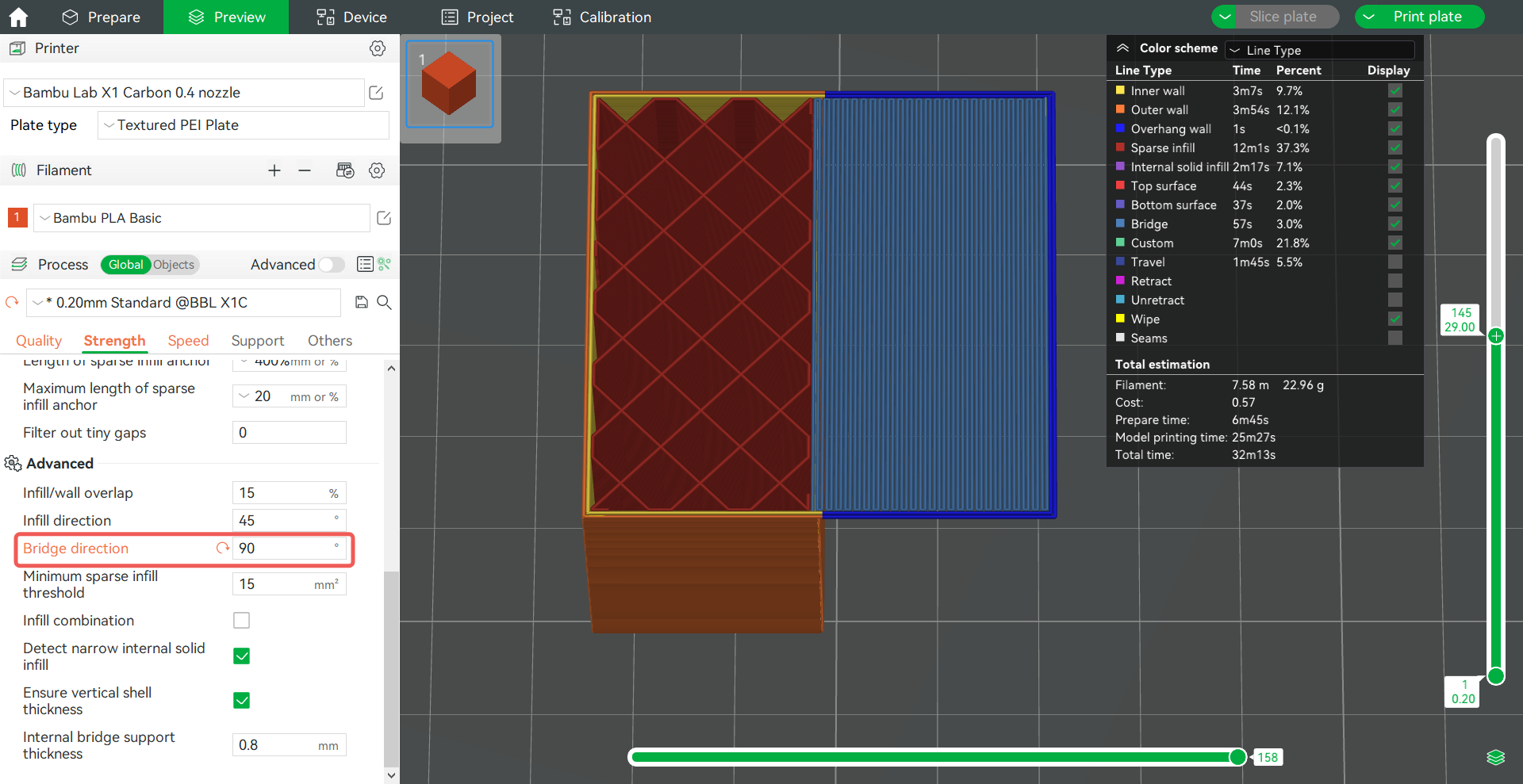
Bridge direction 45°:
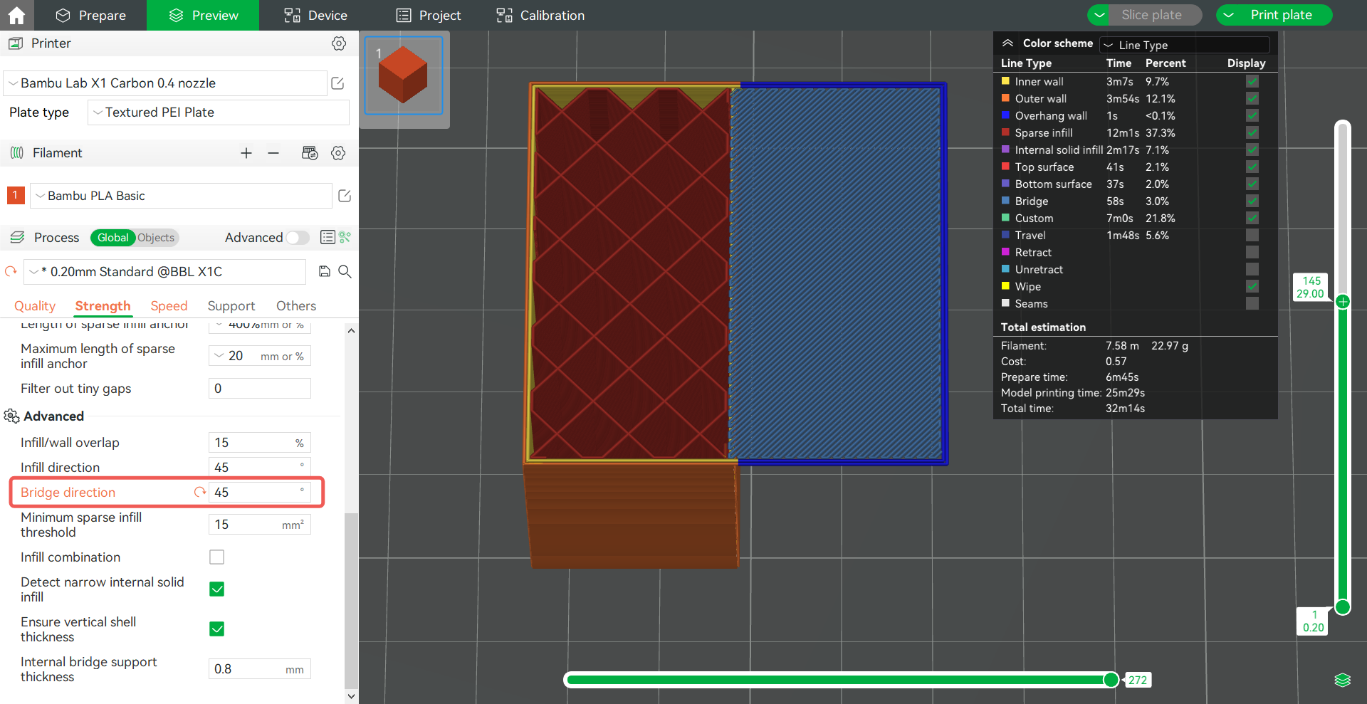
Bridge direction 90°:
