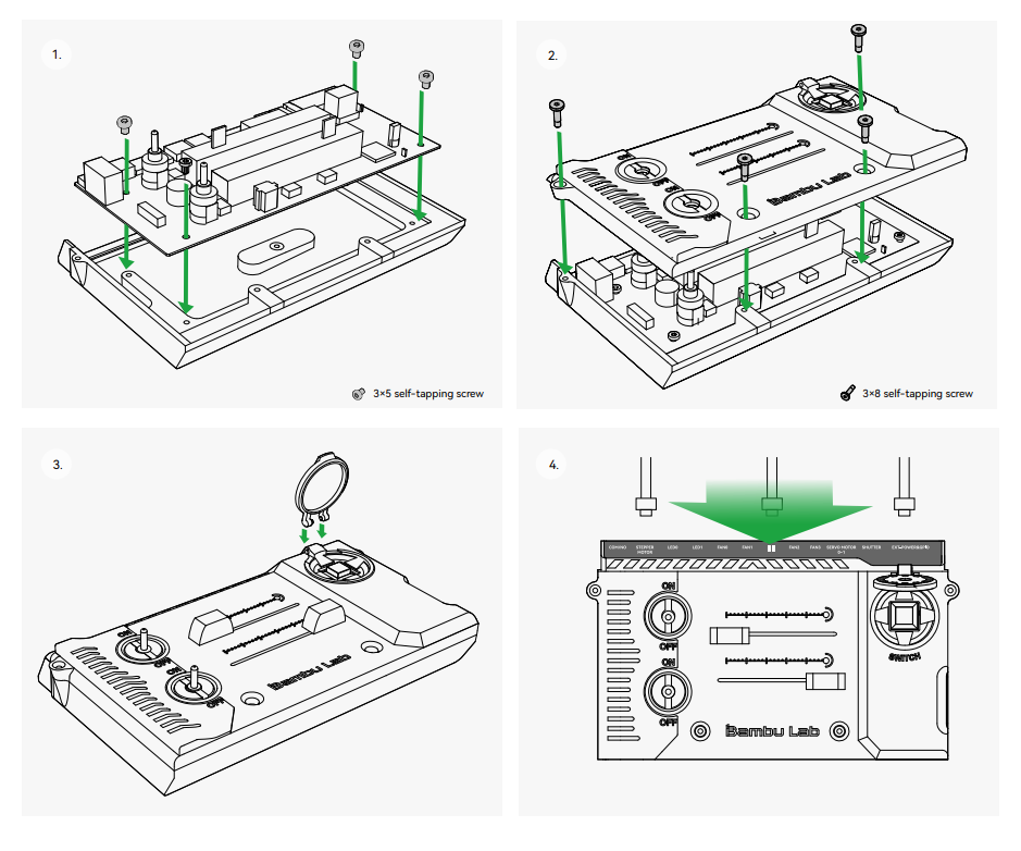
¶ Extension board Enclosure Installation and Interface Description
Bambu Lab Extension Board is a development board designed to add advanced and customized functionalities to Bambu Lab. Before installing the extension board, please make sure that you have read the specifications and compatibility of the board and prepared the necessary tools and materials.


¶ Bambu Lab Extension board Enclosure 3mf File
Please download the Bambu Lab Extension board Enclosure 3mf File from this link.
¶ Bambu Lab Extension board Interface
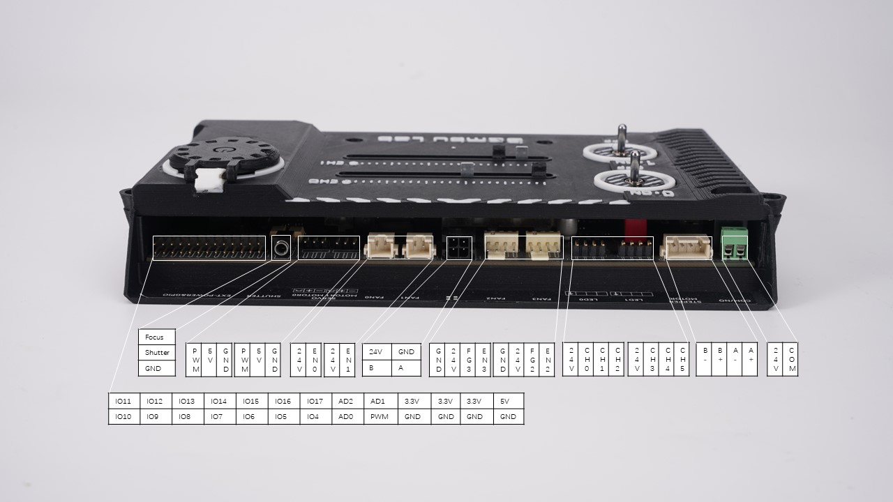
Bambu Lab Extension board Interface contains these functions, like Passive relay connector, Stepper motor connector, RGB LED connector, Fan connector (4 pin), Bus interface, Fan connector (2 pin), Servo connector, Remote shutter connector and Extended I/O. You can make different connectors based on your needs, so as to realize the application of different functions. Tables down below are the descriptions of different connectors in details.

¶ Passive relay connector
| Terminal specification | 2P terminal block with 3.5mm spacing |
| Interface description | Passive mechanical contacts are used to connect and disconnect external circuits and isolate other circuits on the board |
| Line sequence | Common terminal COM, normally open contact NO |
| Switching capacity | Voltage: 30VDC/AC Current: 10A |
| Contact resistance | 20m Ω |
| Wire diameter | 24~18AWG/1.5mm2 |
| Stripping length | 5~6mm |
| Screw hole diameter | 2.8mm |
| Torque | 0.2Nm (1.7 lb. in) |
¶ Stepper motor connector
| Terminal specification | 4P terminal block with 2.54mm spacing |
| Interface description | two single H-bridge drive ICs on board can directly drive the stepping motor |
| Line sequence | A+, A -, B+, B- |
| Load Capacity |
Voltage: 24VDC, Current: 1.5Amax (powered by the host, with 2Amax for the whole board), 3Amax (powered by external 24V, see Appendix 1 for details) |
¶ RGB LED connector
| Terminal specification | 2.54mm spacing 4P round hole pin |
| Interface description | CHn is the same NMOS drain open port |
| Line sequence |
CH5, CH4, CH3, 24V CH2, CH1, CH0, 24V (from left to right) |
| Load Capacity |
Current: 1.5Amax (powered by the host, with 2Amax set outside the whole board), 3Amax (powered by external 24V, see Appendix 1 for details) |
¶ Fan connector(4 pin)
| Terminal specification | 2510 3+1P misplaced bent pin array |
| Interface description | EN has an onboard pull-down resistor and clamped to 3.3V, FG has an onboard pull-up resistor and clamped to 3.3V. |
| Line sequence |
EN2, FG2, 24V, GND EN3, FG3, 24V, GND |
| Load Capacity | 1A max |
¶ Bus interface
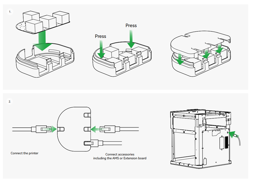
| Terminal specification | 2 * 2P socket with 3mm spacing |
| Interface description | Communicate with the host and draw power from the host |
| Line sequence |
A, B, GND,24V |
| Load Capacity | 2A max |
¶ Fan connector(2 pin)
| Terminal specification | 2P terminal block with 2.54mm spacing |
| Interface description | ENn is NMOS open drain port |
| Line sequence |
EN1, 24V EN0, 24V |
| Load Capacity | 1A max |
¶ Servo connector
| Terminal specification | 3P row pin with 2.54mm spacing |
| Interface description | PWMn is 3.3V level with on-board pull-down resistance |
| Line sequence |
GND, 5V, PWM1 GND, 5V, PWM0 |
| Load Capacity | 1A max |
¶ Remote shutter connector
| Terminal specification | 2.5mm audio socket |
| Interface description | It is isolated from other circuits on the board and connected with the adapter line to control the camera focusing and taking pictures, |
| Line sequence |
GND Shutter shutter focus |
¶ Extended I/O
| Terminal specification | 2.54mm spacing 2 * 13P double row pin |
| Interface description | Extended input/output and A/D ports, check details below |
| Line sequence |
 Notice:IO4~IO11 are 5V level and IO12~IO17 are 3.3V level |
| Load Capacity |
|
| A/D port specification |
|
| PWM port specification |
|
| I/O port Specification |
|
¶ Appendix 1
How to switch to an external 24V power supply to drive a higher-power RGB LED and/or a stepper motor?
a. Keep the power button off (untapped) and the bus interface connected. This indicates that the board is not using the power supply from the bus interface. However, the connection is required to maintain communication between the board and the printer.
b. Connect the external 24V DC power supply with the positive pole( in red arrow) and the negative pole (in green arrow) if needed. There are 6 24V interfaces and 8 GND interfaces for selection to increase available load current and thus the available load power.

Warning: 24V from the bus interface and 24V from the external supply cannot take effect at the same time, otherwise the circuit may be damaged.