¶ Purpose
This wiki provides guidance on how to use ASA-Aero filament to slice and print aircraft models.
¶ Tips and Considerations for Slicing and Printing
- Pre-dry the filament before printing. This helps to remove moisture, and thus avoid holes in the extruded lines.
- Recommended to use high temperatures and low print speeds. This helps to ensure proper foaming and adhesion of ASA Aero.
- Recommend to use Engineering Plate or Smooth PEI Plate (High Temperature Plate). Not Recommend to use Textured PEI Plate, and this is to prevent its uneven texture from causing the first layer of some models to be overly sticky to the plate, causing partial damage to the bottom surface or tearing at the weak points of the first and second layers of them when removing them after printing.
- Avoid using excessively low or high fan speeds during printing . This helps to ensure sufficient cooling without excessive cooling, balancing the quality of the surface finish and interlayer adhesion.
- Pungent and unpleasant odors can be released during printing. Make sure your printer is enclosed and placed in a well-ventilated area.
- Just like normal ASA, ASA Aero is prone to warping when printing large size and/or high infill density model. To avoid warping: (1) Not recommended to print too large size and/or high infill density models. (2) Use enclosure printers and ensure the build plate is properly glued before printing. (3) Set lower printing speed and higher heatbed temperature. For more details please refer to: Common print quality problems and solutions on WIKI.
Whenever possible, print a single model at a time or printing by object to print a small number of models at once. Avoid printing by layer to print multiple models at once, as it may result in stringing, oozing, and other defects due to empty travel and jumping areas.
Note that when printing aircraft models, due to the diversity of model structures and sizes, the default recommended print parameters may not perfectly fit all models. Therefore, multiple parameter adjustments and test prints may be required for certain models.
The average density of prints will vary depending on actual printing temperature, print speed, flow rate, model size, wall thickness (wall loops), and infill density. The general relationship is shown in the table below:
|
Parameter |
Printing Temperature |
Printing Speed |
Flow Ratio |
Model Size |
Wall Thickness (wall loops) |
Infill Density |
|
Parameter Variation |
Increase |
Increase |
Increase |
Increase |
Increase |
Increase |
|
Average Density Variation |
Decrease |
Unchanged/Increase |
Increase |
Decrease |
Increase |
Increase |
The relationship between the maximum foaming ratio, minimum printing model density, and printing temperature for Bambu ASA Aero is approximately as follows:
|
Printing Temperature / ℃ |
220 |
230 |
240 |
250 |
260 |
270 |
280 |
|
Minimum Flow Ratio |
~ 0.93 |
0.90 |
0.74 |
0.60 |
0.51 |
0.45 |
0.44 |
|
Maximum Volumetric Expansion Ratio |
~ 100% |
106% |
128% |
158% |
186% |
211% |
216% |
|
Maximum Foaming Ratio |
~ 0% |
6% |
28% |
58% |
86% |
111% |
116% |
|
Minimum Prints Density / (g/cm³) |
~ 0.97 |
0.92 |
0.78 |
0.61 |
0.52 |
0.46 |
0.45 |
Note:
(1) Test parameters: the Nozzle size is 0.4 mm, the print speed of 80 mm/s, and the model size is length * width * height = 80 * 10 * 4 mm³ (the XY direction).
(2) The actual required flow ratio and final model density may vary for different models.
¶ Slicing parameter settings (Image example for recommended parameters for a 0.4 mm nozzle):
¶ 1. Use the default Bambu ASA Aero parameters
Note:
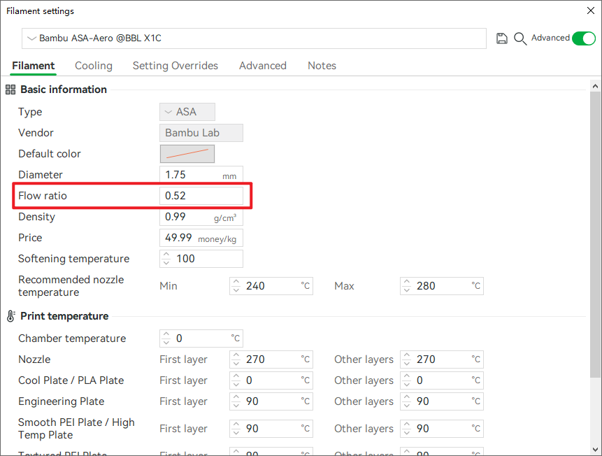
Due to the high foaming ratio of ASA Aero, it is recommended to adjust the flow ratio based on the actual model when printing.
Recommended Flow Ratio: 0.42 - 0.7.
¶ 2. Process Quality Parameter Adjustments
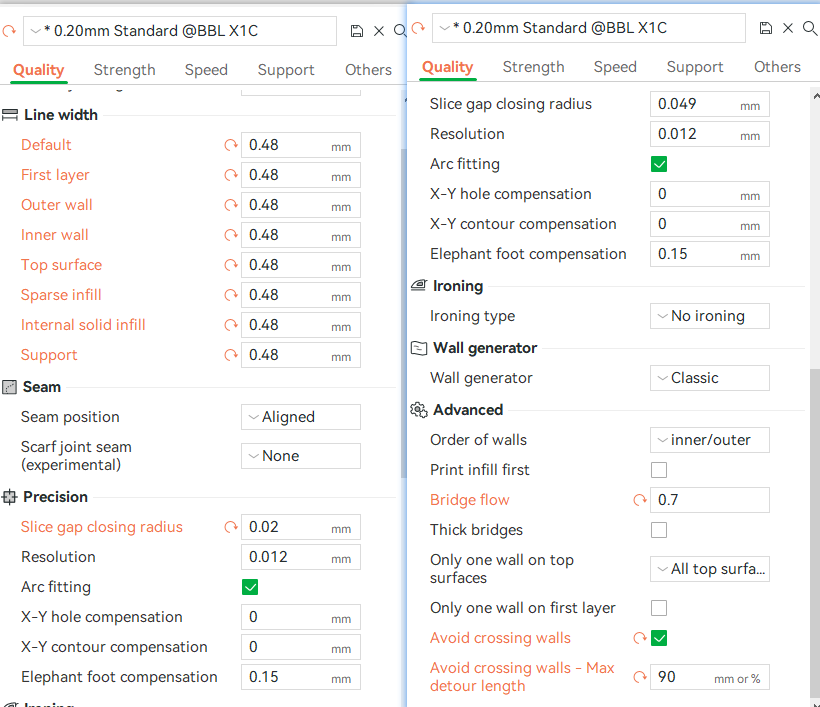
Line width: set to 0.48 mm,
Slicing gap closing radius: set to 0.02 mm,
Bridge flow: set to 0.7,
Check the option to avoid crossing walls with a maximum detour length of 90%.
¶ 3. Process Strength Parameter Adjustments:
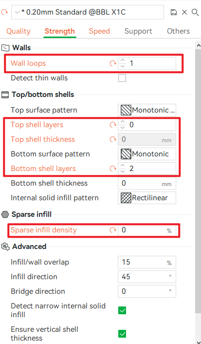
Wall loops: set to 1;
Top shell layers: set to 0,
Top shell thickness: set to 0 mm (adjust when top is enabled);
Bottom shell layers: set to 2;
Sparse infill density: set to 0%.
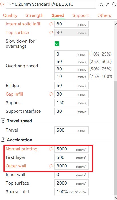
¶ 4. Process Speed/Acceleration Parameter Adjustments:
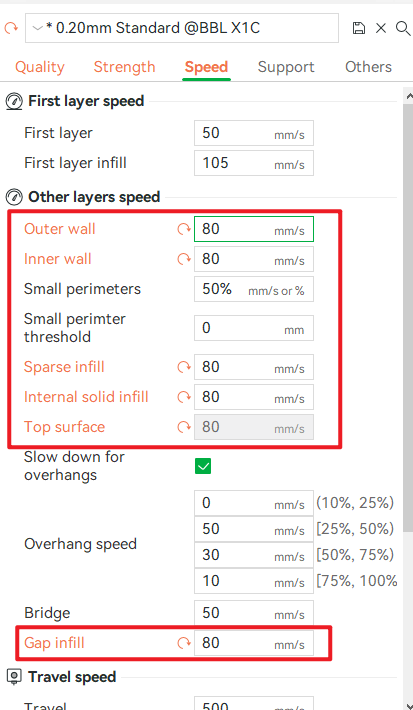
Outer wall, inner wall, sparse infill, internal solid infill, top surface (when enabled), and gap infill speeds: all set to 80 mm/s.
Normal printing acceleration: set to 5000 mm/s,
Outer wall acceleration: set to 3000 mm/s.
 |
 |
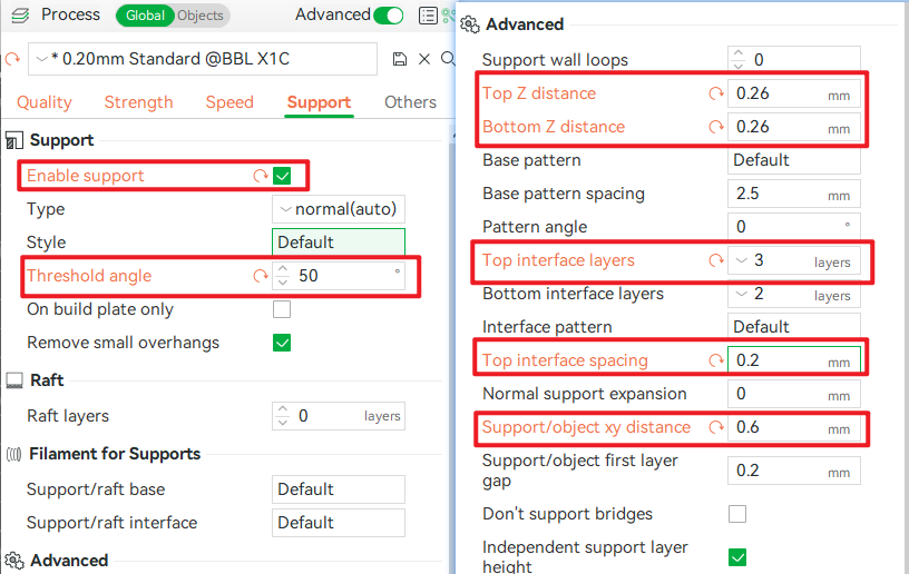
¶ 5. Process Support Parameter Adjustments (to be enabled when necessary; not recommended for regular model aircraft printing):
Threshold angle: set to 50°;
Top/bottom Z distance: set to 0.26 mm;
Top interface layers: set to 3;
Top interface spacing: set to 0.2 mm;
Support/object xy distance: set to 0.6 mm
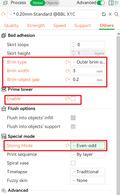
¶ 6. Other Process Parameter Adjustments:
Brim type: set to outer brim only;
Brim width: set to 3 mm;
Brim-object gap: set to 0.2 mm;
Power tower: disabled;
Slicing mode: set to Even-odd.
¶ Default Profiles
Download and open the following 3MF files and import them into the model to obtain pre-configured printing parameters.
When using a different printer model, you can transfer the corresponding process parameters and filament settings mentioned below:
X1C 0.4 mm nozzle: ASA-Aero.3mf