¶ AMS lite AMS Feeder Units
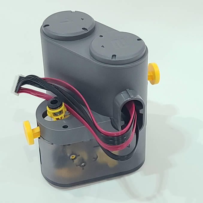
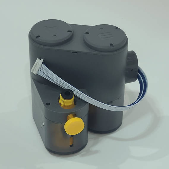
This article provides guidelines and precautions for the disassembly and assembly of the AMS Feeder Units.
 |
 |
¶ Parts List
The following are the after-sales individual items that will be involved in this guide.
| No. | Name | Image | No. | Name | Image |
|
1 |
AMS Left Feeder Unit (1 and 2) |
 |
2 |
AMS Right Feeder Unit (3 and 4) |
 |
|
3 |
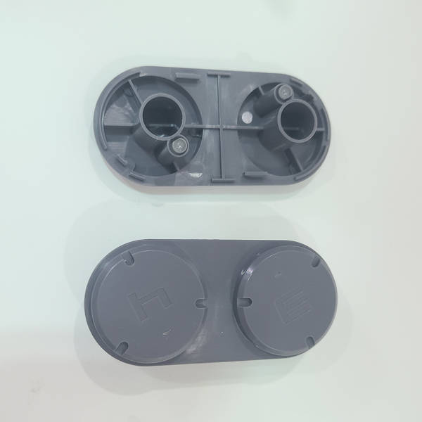
AMS Feeder Cap |
 |
4 |
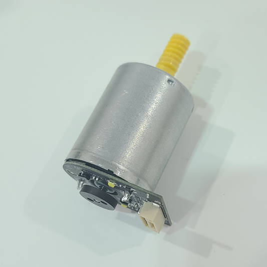
AMS Feeder Motor Components |
 |
|
5 |
AMS Filament Funnel Unit - Left |
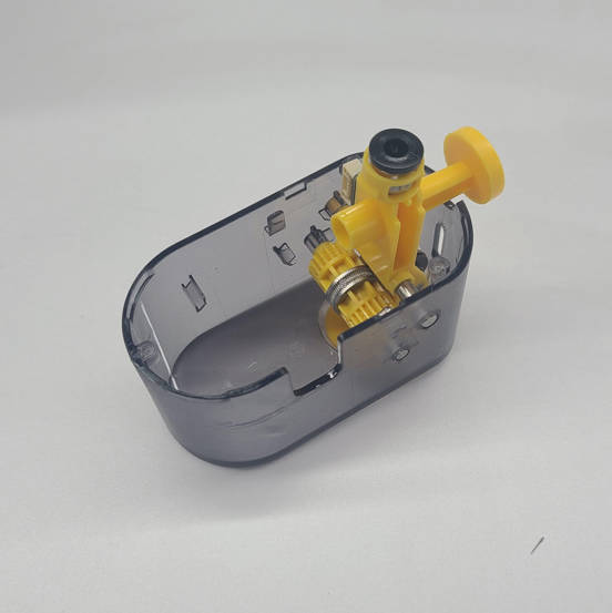 |
6 |
AMS Filament Funnel Unit - Right |
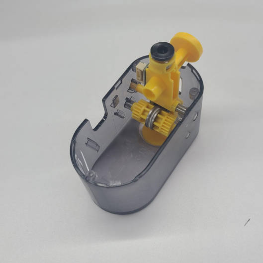 |
¶ Assembly List
None
¶ Screw List
| Model | Position | Drawing | Model | Position | Drawing | ||
| Screw A |
M3*5 B0010 |
To lock the motor: 4PCS |
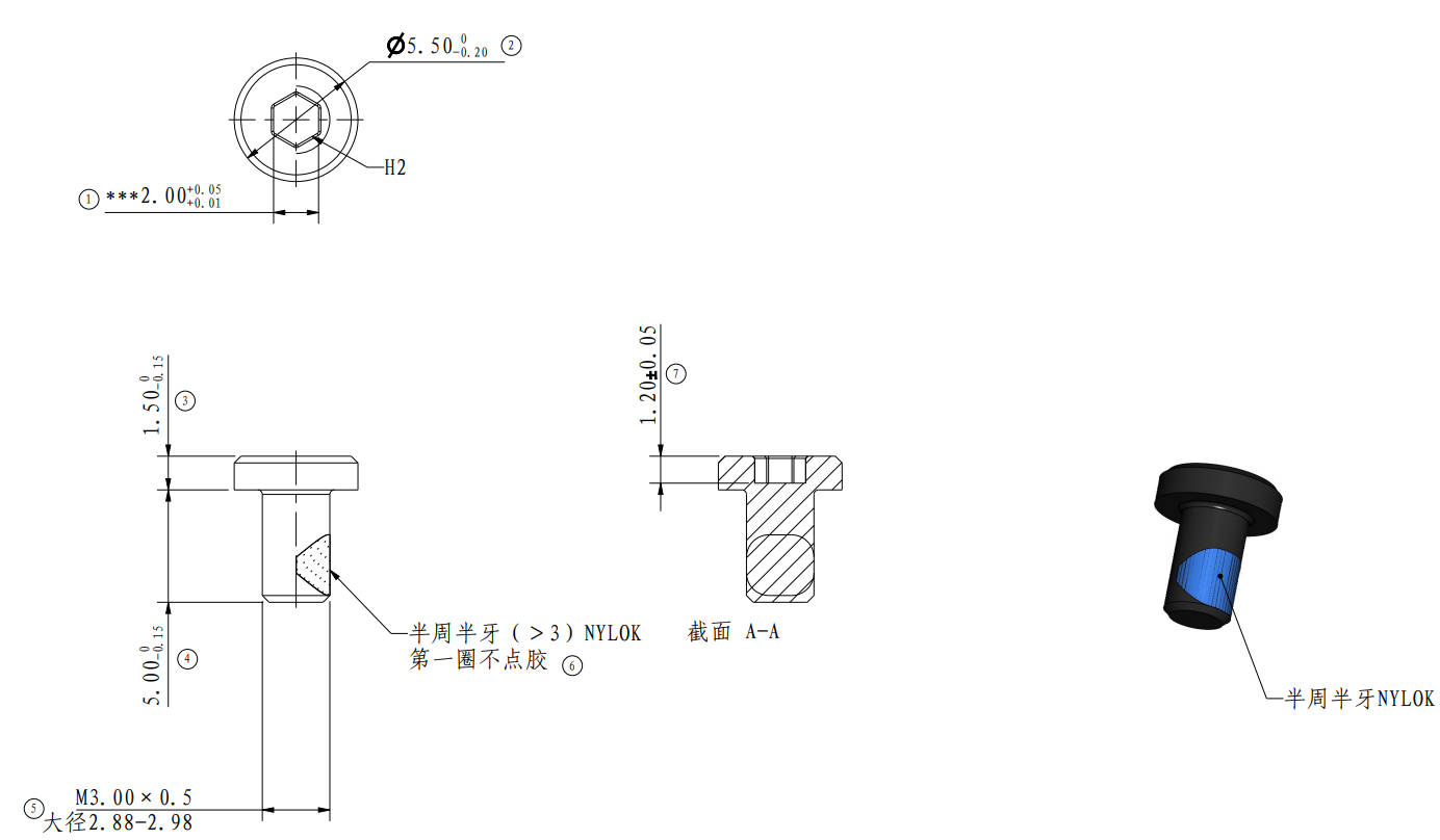 |
Screw A |
BT2*13 B00200 |
To lock the AMS Filament Funnel Unit:6PCS |
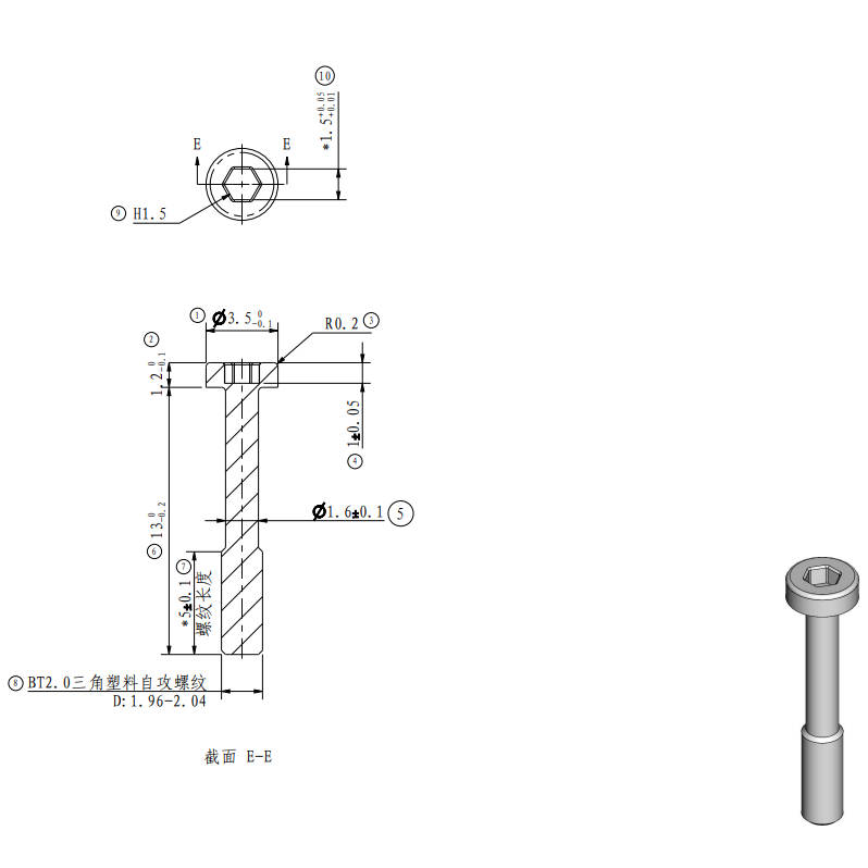 |
¶ Tool List
Flat Head Tweezers
H1.5 /H2.0 Hexagonal Wrench
¶ Previous Operation
If needed, please refer to the AMS Lite installation tutorial to learn how to remove and install the AMS Lite Feeder Unit from the AMS Lite.
¶ Safety Warning
IMPORTANT!
It's crucial to disconnet the AMS Lite from the printer before performing any maintenance work on the AMS and its electronics, because leaving the AMS connected while conducting such tasks can cause a short circuit, which can lead to additional electronic damage and safety hazards.
If you have any concerns or questions about following this guide, open a new ticket in our Support Page and we will do our best to respond promptly and provide you with the assistance you need.
¶ Video Guide
¶ Disassemble the AMS Feeder Unit
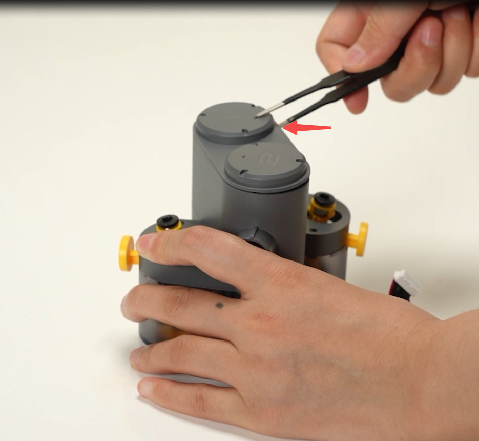
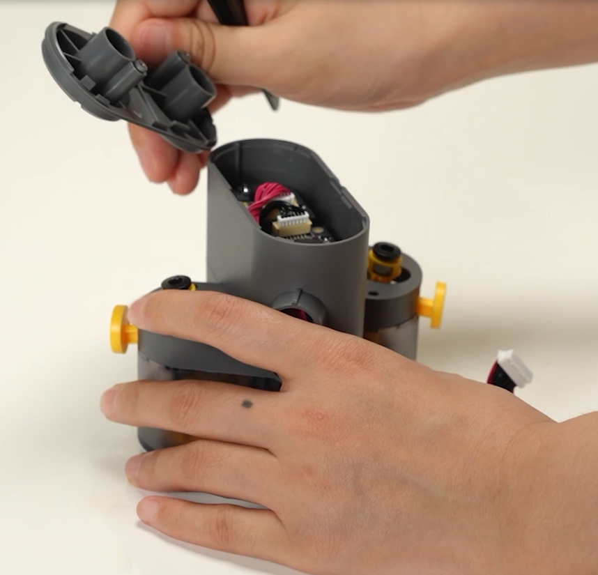
¶ Step1 - Remove the AMS Feeder Cap
Use flat-tipped tweezers to pry the top cover from its notched position and remove it.
 |
 |
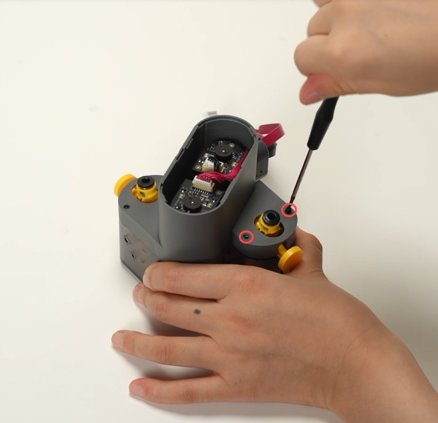
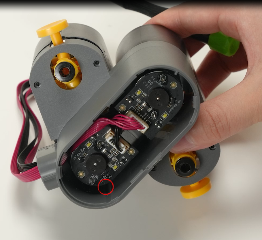
¶ Step 2 - Remove the AMS Filament Funnel Unit
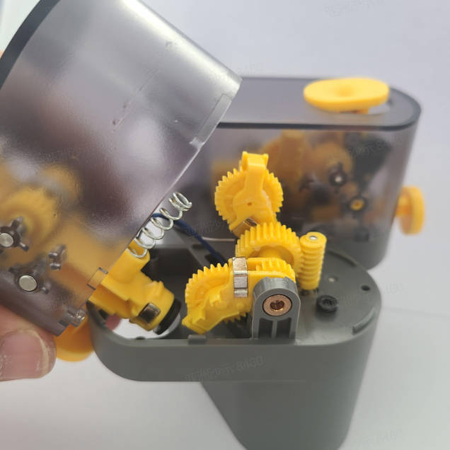
Unscrew the 3 screws B with an H1.5 Allen key to loosen the Filament Funnel Unit, disconnect the wire connections, and remove the spring.
 |
 |
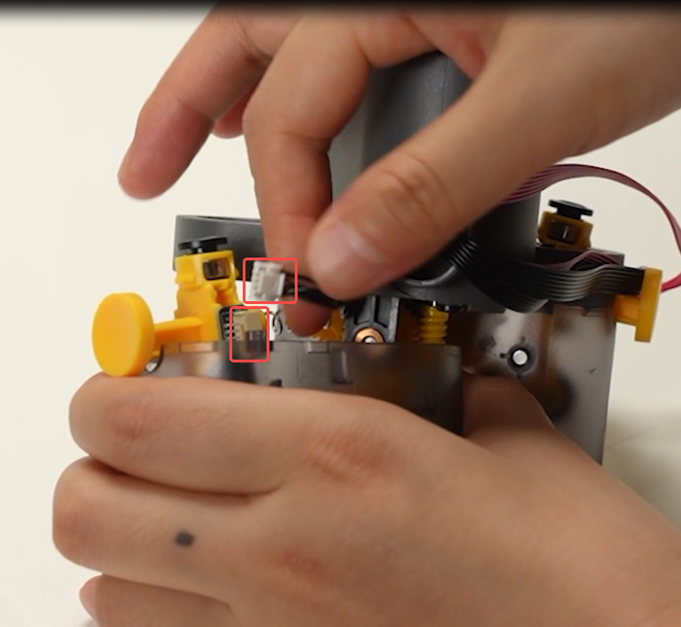 |
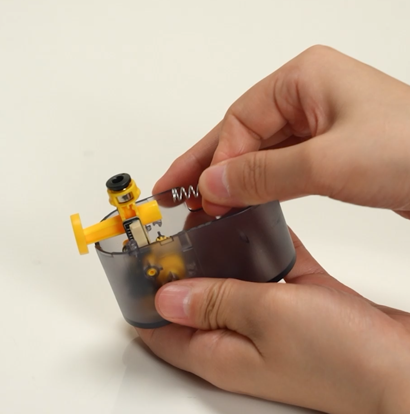 |
Repeat the above steps to remove the other AMS Filament Funnel Unit.
¶ Step 3 - Remove the AMS Feeder Motor Components
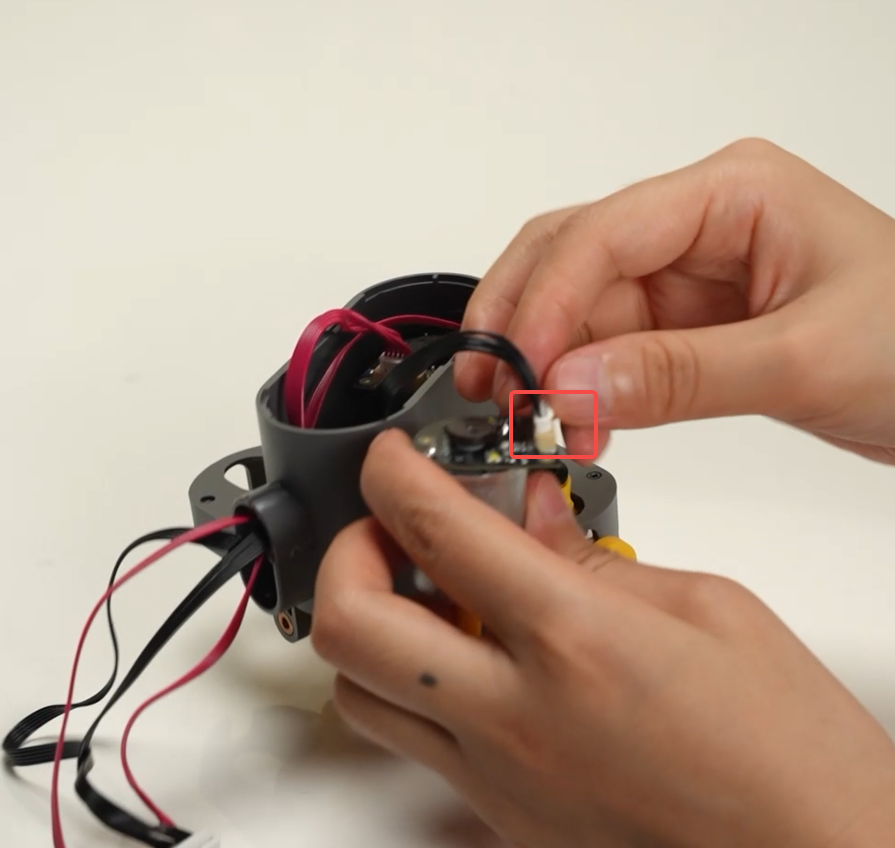
Disconnect the AMS Feeder motor's connecting wires and remove the motor by removing the 2 screws A with an H2.0 Allen key.
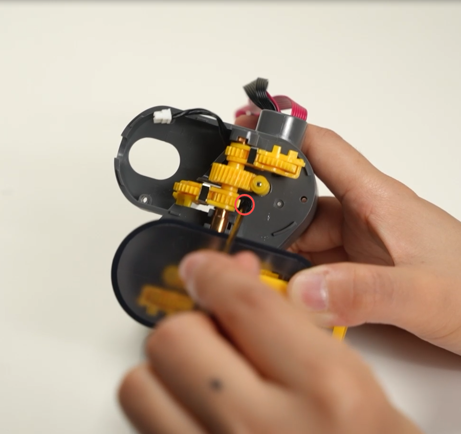 |
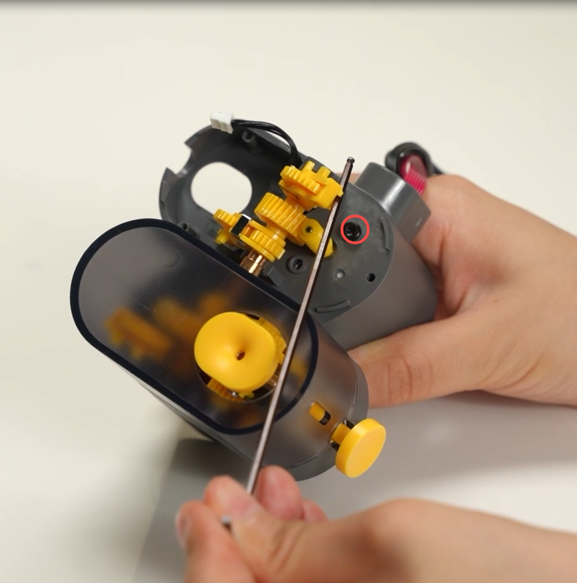 |
 |
Repeat the above steps to remove the other AMS Feeder Motor Components.
¶ Assemble the AMS Feeder Unit
¶ Step1 - Install the AMS Feeder Motor
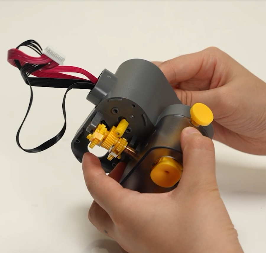
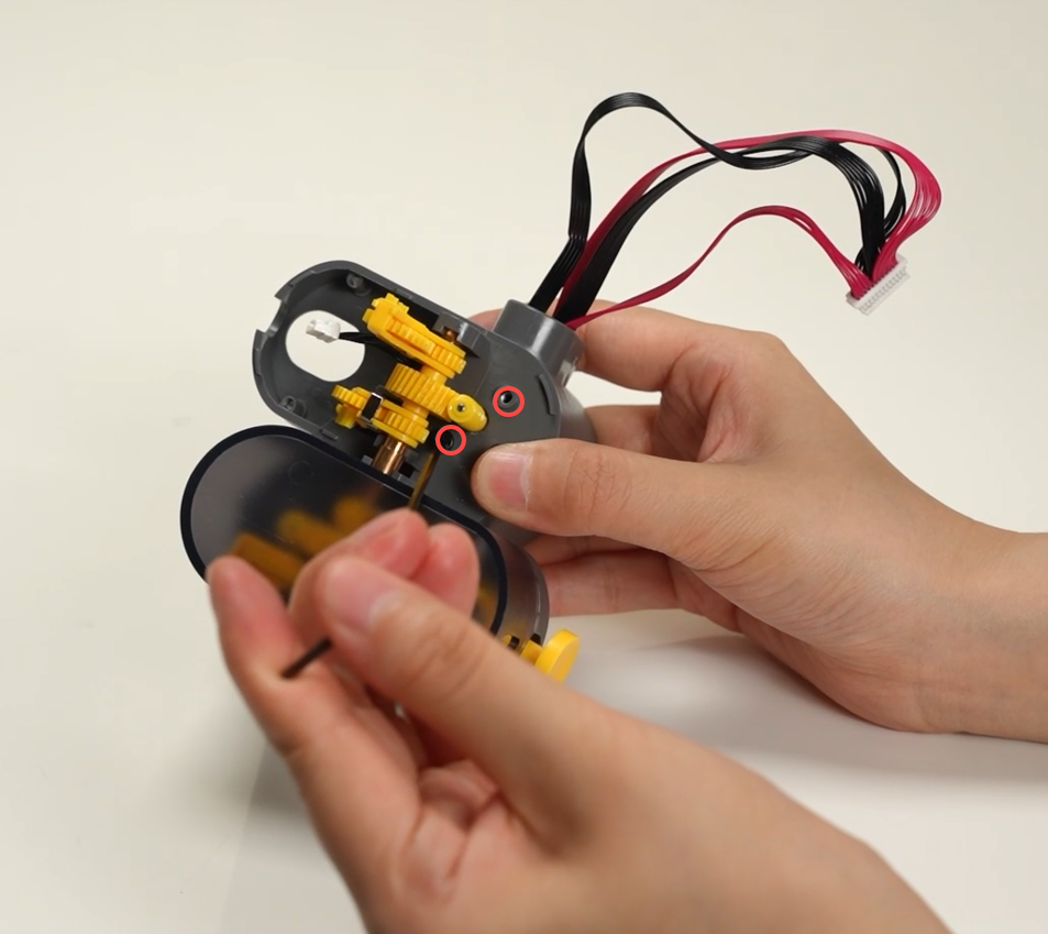
Connect the cables and install the motor inside the AMS Feeder, then lock in 2 screws A with an H2.0 Allen key.
 |
 |
 |
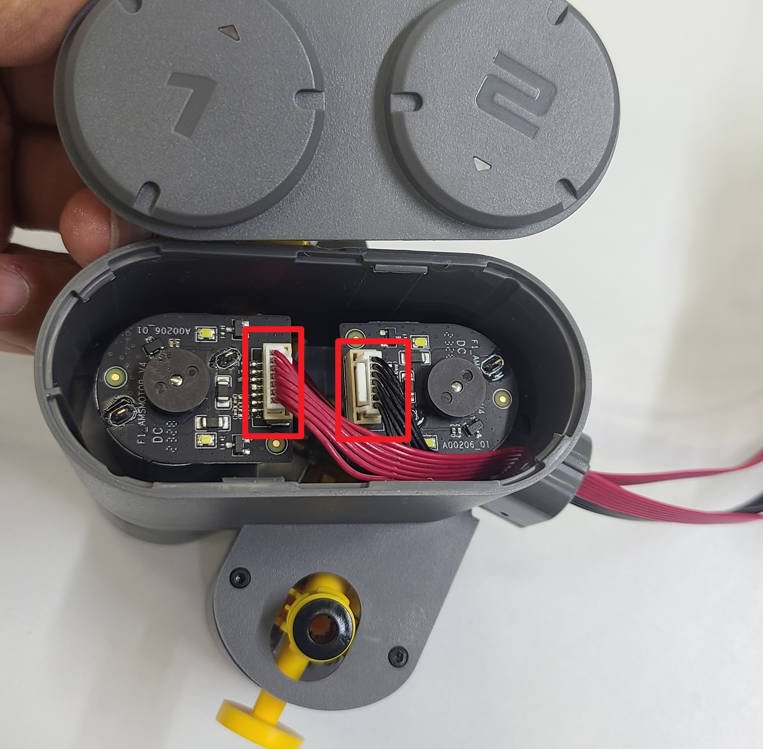
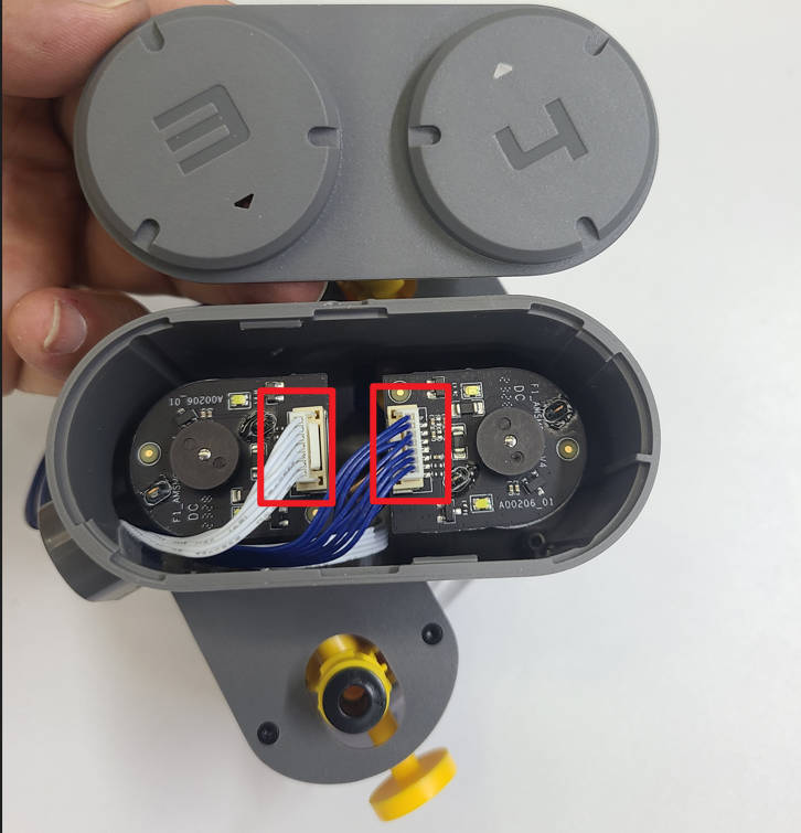
Repeat the above steps to install the other AMS Feeder Motor. Please make sure that the two cables with different colors should be connected to the right connectors shown below.
 |
 |
¶ Step 2 - Install the AMS Filament Funnel Unit
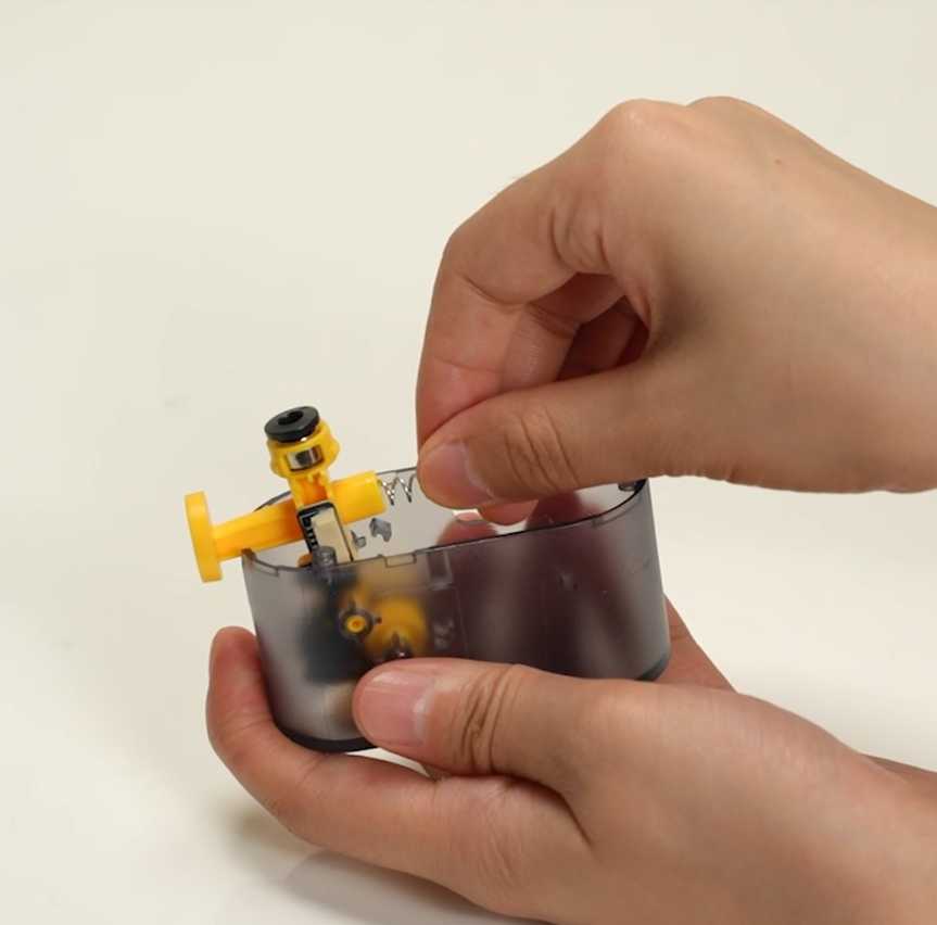
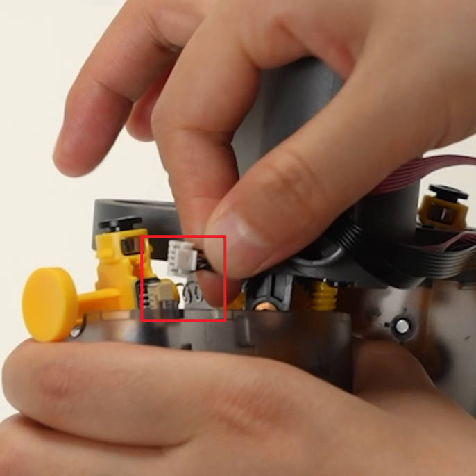
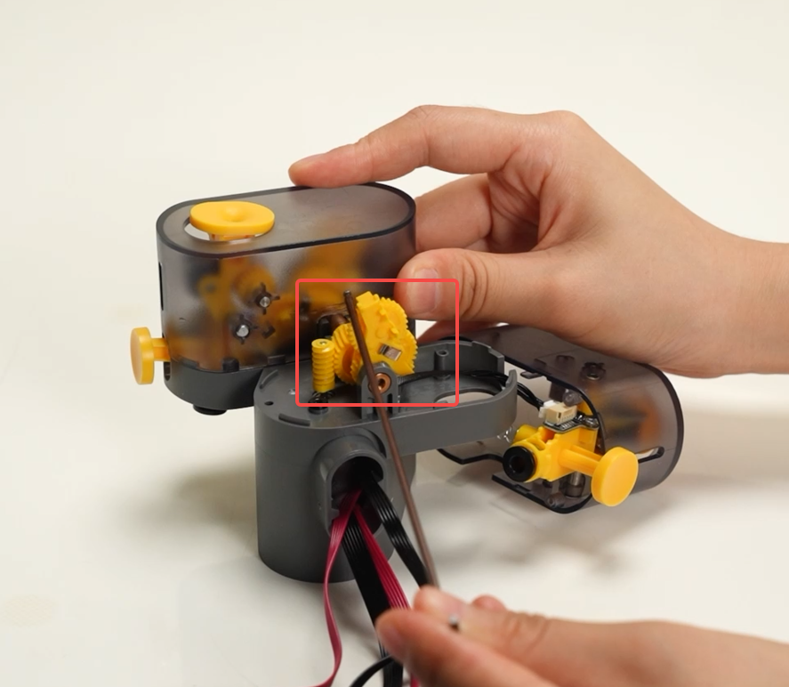
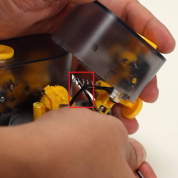
Install the spring onto the AMS Filament Funnel Unit-Left, connect the cable, and adjust the position of the swing gear set as shown in the figure. The inner gear should be turned to the right and the outer gear should be upright;
|
 |
 |
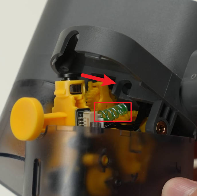
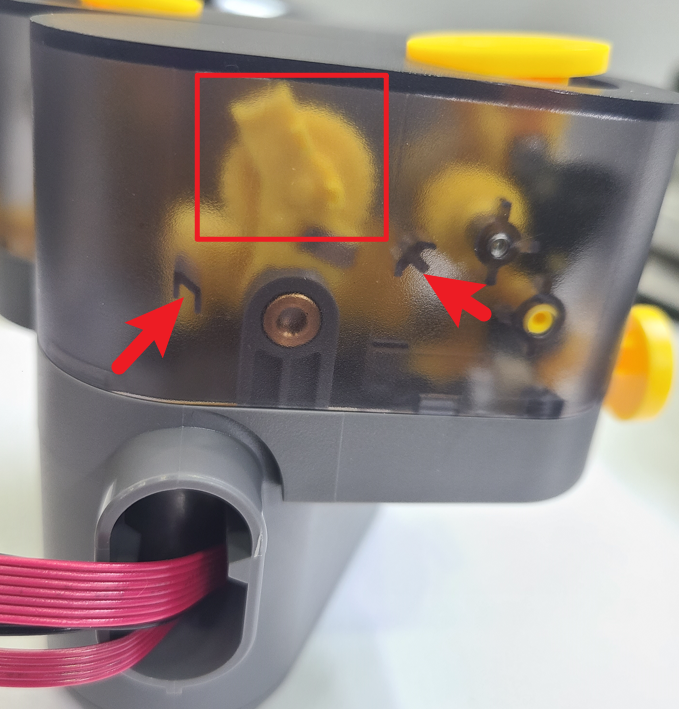
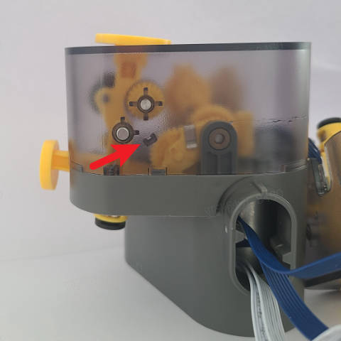
Install the AMS Filament Funnel Unit-Left, place the other end of the spring in place with the help of the hex key, and pay attention to the outer swing gear set being between two limit blocks. The inner swing gear should be placed under the limit block, and then buckled in place;
 |
 |
 |
Screw in 3 screws B to lock the AMS Filament Funnel Unit-Left.
 |
 |
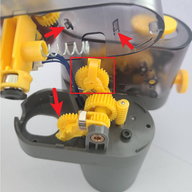
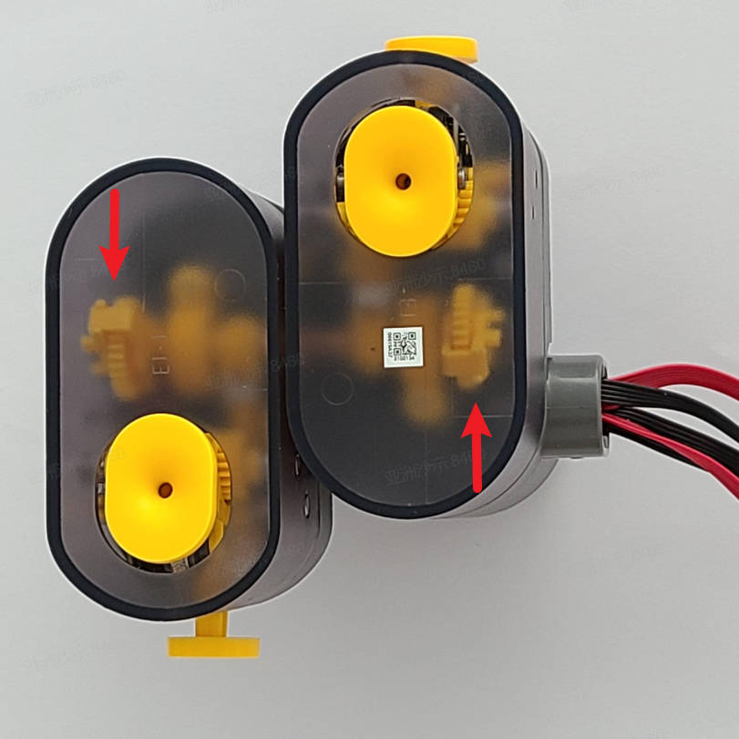
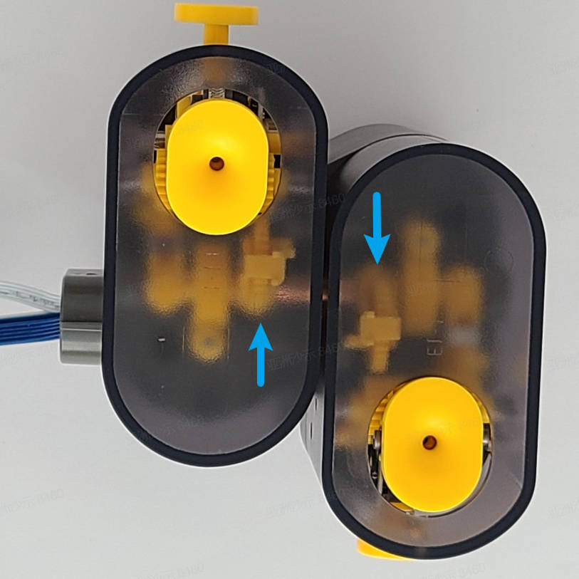
A similar operation can be used to install the AMS Filament Funnel Unit-Right. However, you need to pay attention to the installation position of the gear sets. This installation position is somewhat different from the AMS Filament Funnel Unit-Left. Please see the picture below for details and refer to this wiki.
 |
 |
 |
The final installation effect is shown below:
 |
 |
¶ Step 3 - Install the AMS Feeder Cap
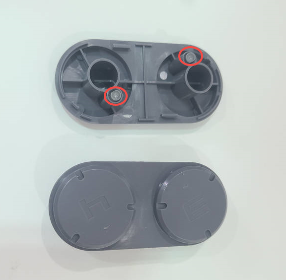
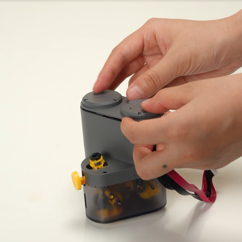
Check whether the light guide column is in position; Confirm the installation direction and install the AMS Feeder Cap.
 |
|
¶ Verify the functionality
Push the AMS Filament Funnel Rod by hand to confirm movement and smoothness.
¶ Calibration
Not required
¶ End Notes
We hope that the detailed guide we shared with you was helpful and informative.
We want to ensure that you can perform it safely and effectively. If you have any concerns or questions regarding the process described in this article, we encourage you to reach out to our friendly customer service team before starting the operation. Our team is always ready to help you and answer any questions you may have.
Click here to open a new ticket in our Support Page.
We will do our best to respond promptly and provide you with the assistance you need.