¶ Phenomenon
The actual heatbed temperature is displayed as 0 ℃, or the heatbed does not heat up after setting a temperature.
¶ Causes & Solutions
For the A1 printer, you can determine the faulty component based on the HMS codes provided on the assistant page without disassembling the machine.
If the assistant page indicates any of the following three HMS error codes, the likely cause of the fault is the hotbed temperature sensor. If you have checked for loose connectors and found none, the fault is likely with the hot bed unit.
In rare cases, the HMS assistant page may display one of the following three HMS codes. However, if the NTC resistance measured below is within the normal range, this suggests that the fault type is due to a poor connection. In this case, the fault is still likely with the hotbed assembly.
- HMS_0300-0100-0001-0007: The heatbed temperature is abnormal; the sensor may have an open circuit.
- HMS_0300-0100-0001-0006: The heatbed temperature is abnormal; the sensor may have an short circuit.
- HMS_0300-0100-0001-0003: The heatbed temperature is abnormal; the heater is over temperature.
If the assistant page indicates, " An abnormality occurs during the heating process of the heatbed. The heating modules may be broken," the likely cause of the fault is the hot bed heating modules. If you have checked for loose connectors and found none, then the fault is likely with the hotbed assembly or the AC board.
- HMS_0300-0100-0001-0008: An abnormality occurs during the heating process of the heatbed. The heating modules may be broken.
This article will guide you on how to check the cable connections and use a multimeter to further assist in diagnosing why the hot bed cannot heat or why the bed temperature is zero.
It should be noted, as mentioned above, that the NTC resistance measured with the multimeter is for reference only. If the NTC resistance deviates from the normal range, it indicates that the hotbed unit is abnormal; however, if the NTC resistance measures normally, the hot bed unit may still have issues.
¶ Tools and Materials Required
- H2.0 Allen key (used to loosen the screws on the baseplate)
- Tweezers (used to remove the insulation sleeve and cables)
- Multimeter
¶ Safety Warning
IMPORTANT!
It's crucial to power off the printer before performing any maintenance work on the printer and its electronics, including tool head wires, because leaving the printer on while conducting such tasks can cause a short circuit, which can lead to additional electronic damage and safety hazards.
When you perform maintenane or troubleshooting on the printer, you may be required to disassemble some parts, including the hotend. This process can expose wires and electrical components that could potentially short circuit if they come into contact with each other or with other metal or electronic components while the printer is still on. This can damage the electronics of the printer and cause further damage.
Therefore, it's essential to switch off the printer and disconnect it from the power source before doing any maintenance work. This will prevent any short circuits or damage to the printer's electronics. By doing so, you can avoid potential damage to the printer's electronic components and ensure that the maintenance work is performed safely and effectively.
If you have any concerns or questions about following this guide, open a new ticket in our Support Page and we will do our best to respond promptly and provide you with the assistance you need.
During the troubleshooting process, please avoid applying an external force to the heatbed cable to prevent any impact on its lifespan.

¶ Steps for Troubleshooting
¶ Step 1: First, disconnect the power supply off the printer's power switch. Remove the three plugs from the cable box and dismantle the bottom cover(half) of the printer.
This article only provides guidelines and precautions for measuring heatbed resistance. For guidelines on disconnecting the motor connection cable from the AC board, please refer to “Step 2- Disconnect the cables” of the “A1 Disassembly” in A1 Installation Tutorial | Bambu Lab Wiki.
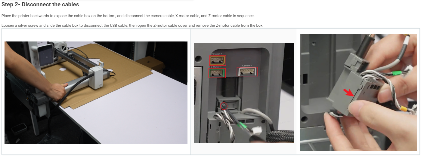
Note: In this step, there is no need to open the Z-motor cable cover of the cable box. Simply slide the cable box to disconnect the USB cable.
After disconnecting the connection cable, use an H2.0 Allen key to remove the 10 screws indicated by red dots on the bottom cover shown in the diagram below. Lift and remove the printer's bottom cover from the left edge, exposing the measurement location of the AC board as illustrated. The position of the AC board is shown in the diagram.
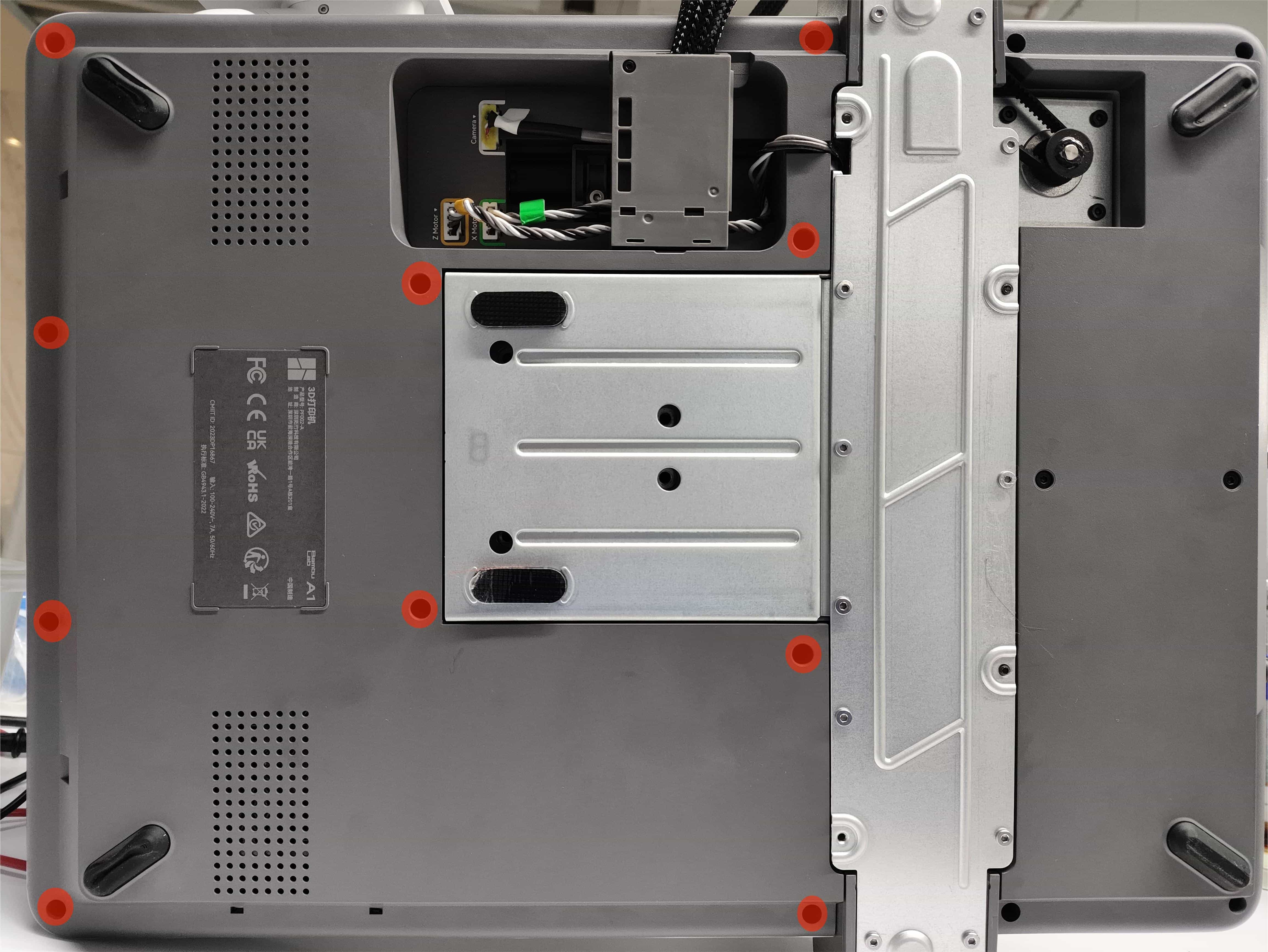 |
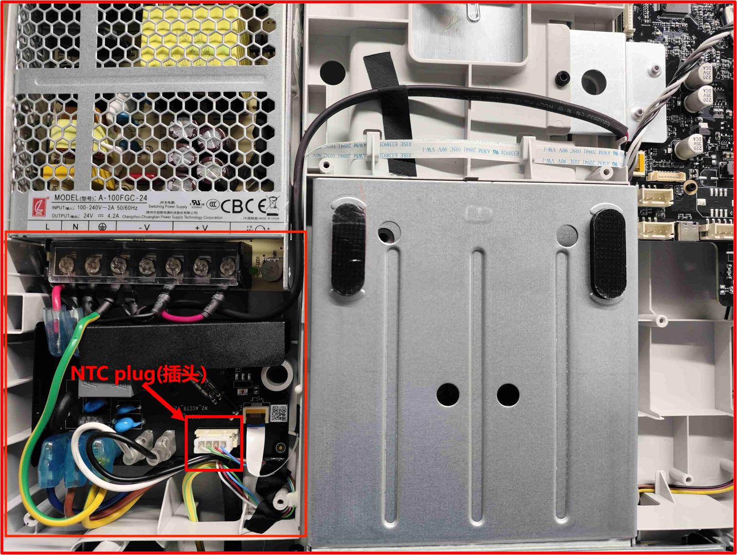 |
After removing the bottom cover, please first check if the temperature sensor (NTC sensor)plug for the heatbed is loose, as previous cases have shown that it may become detached during transportation. If you find the plug loose, please reinsert it into the socket according to its orientation, then reinstall the bottom cover and restart the printer to see if the issue has been resolved.
Note: It is not necessary to remove the heatbed assembly from the printer during resistance measurement.
¶ Step 2: Measure the resistance of temperature sensor connector(NTC sensor)
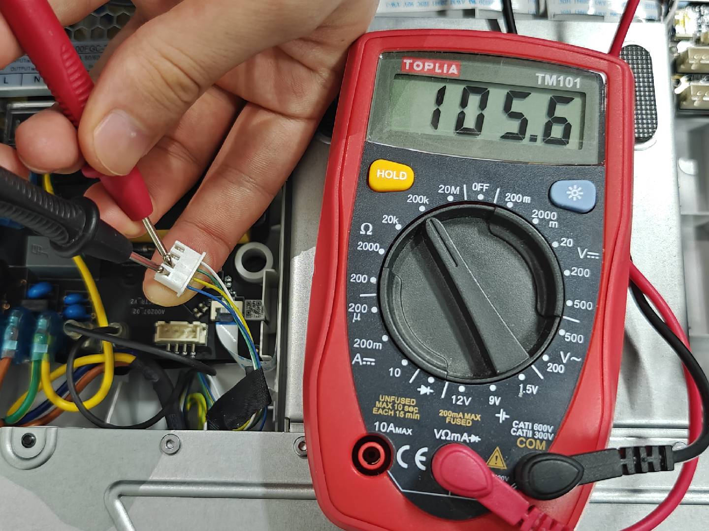
If the resistance measured at this point is around 100 kΩ (it may vary with the ambient temperature; a slight deviation is acceptable, and the measured value in the graph is 105.6 kΩ), the heatbed's NTC sensor and temperature sensing cables are functioning properly.
Important Note: To perform the measurement at this point, use a tweezer to disconnect the heatbed NTC cable. As shown in the diagram, the measurement location is at the yellow and blue wire connection ports on the NTC cable.
(This diagram is for reference purposes only to indicate the measurement points for heatbed resistance. It is not necessary to remove the components from the printer base during the measurement process)
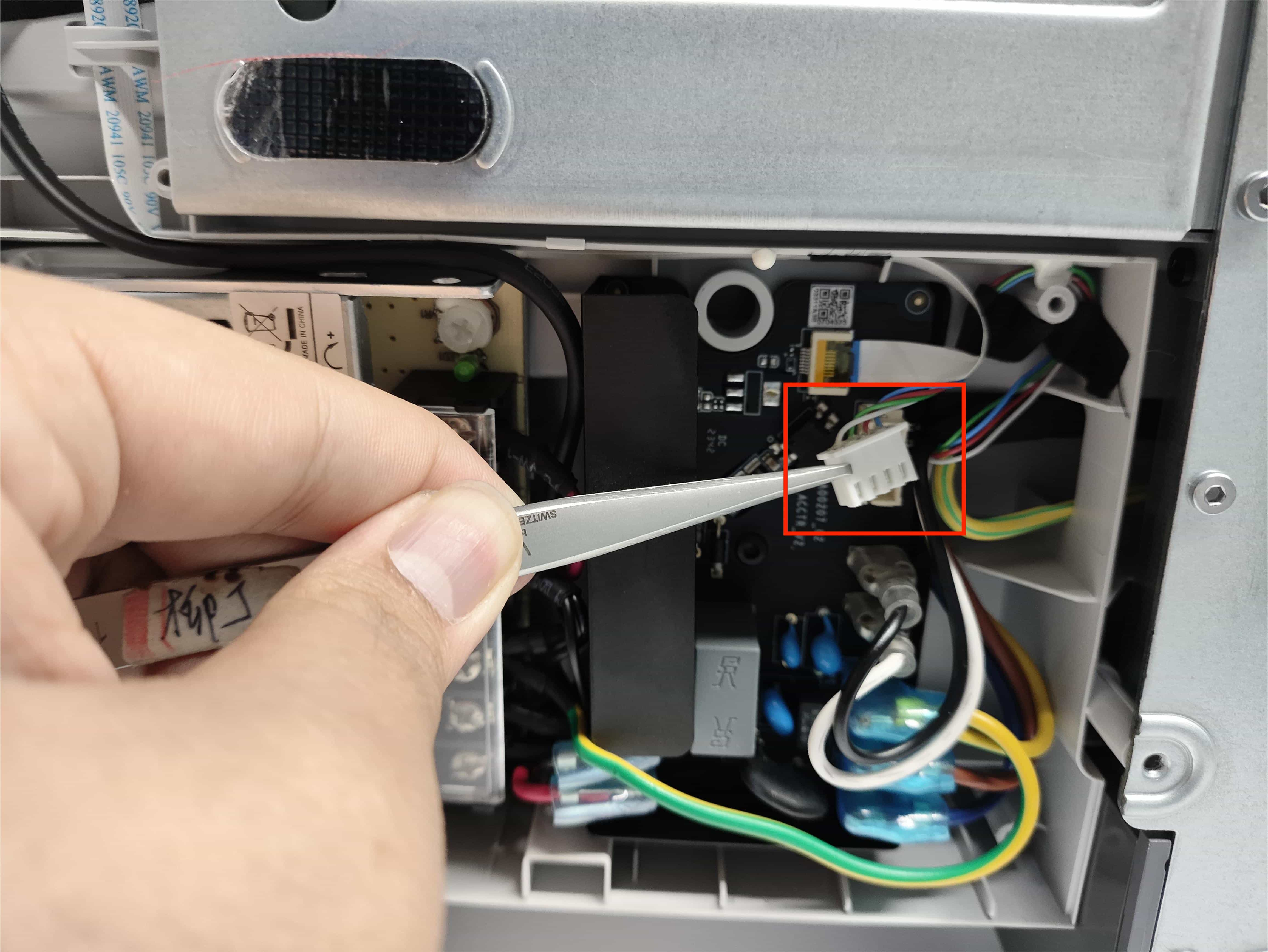 |
 |
¶ Step 3: Measure the resistance of the heatbed power supply connector
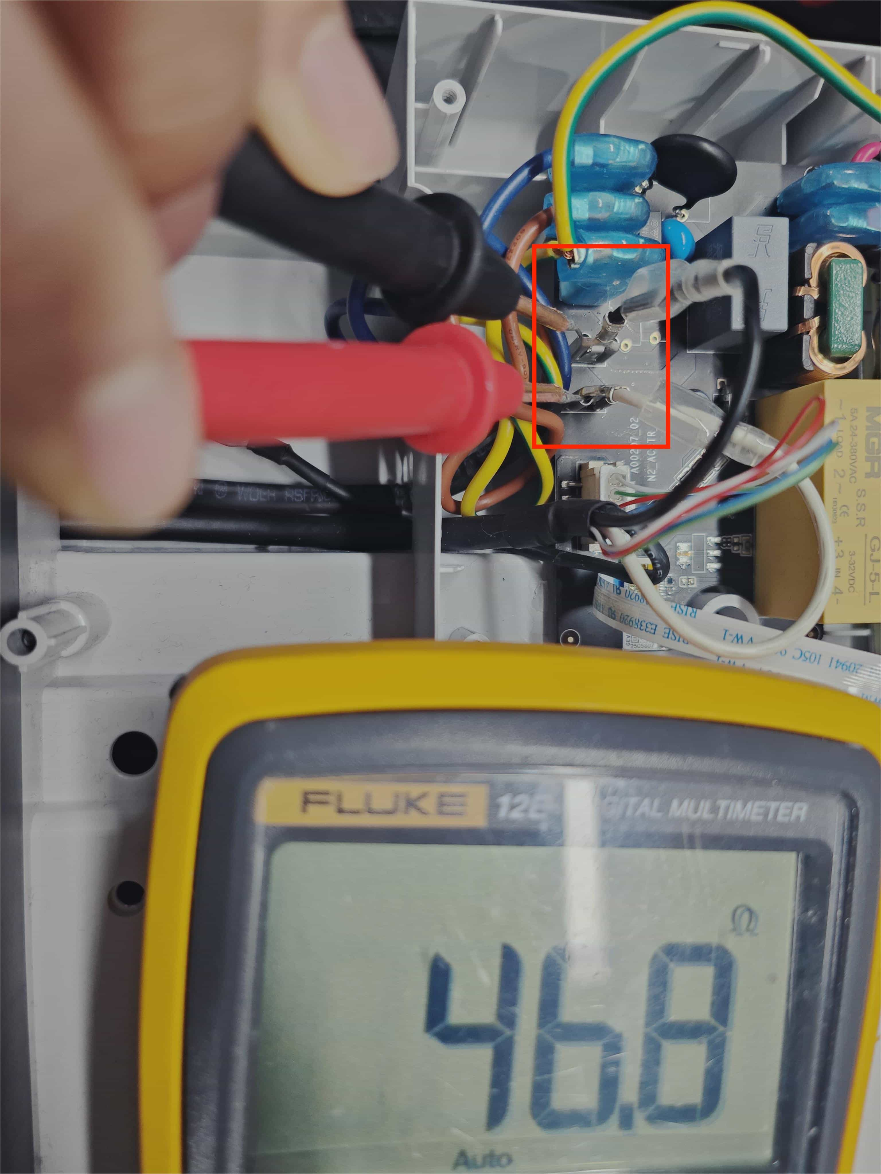
If the resistance measured at this point is 45Ω~50Ω (it may vary with the ambient temperature; a slight deviation is acceptable, and the measured value in the graph is 47.5 Ω), it indicates that the heatbed heating part and power cables are functioning properly.
 |
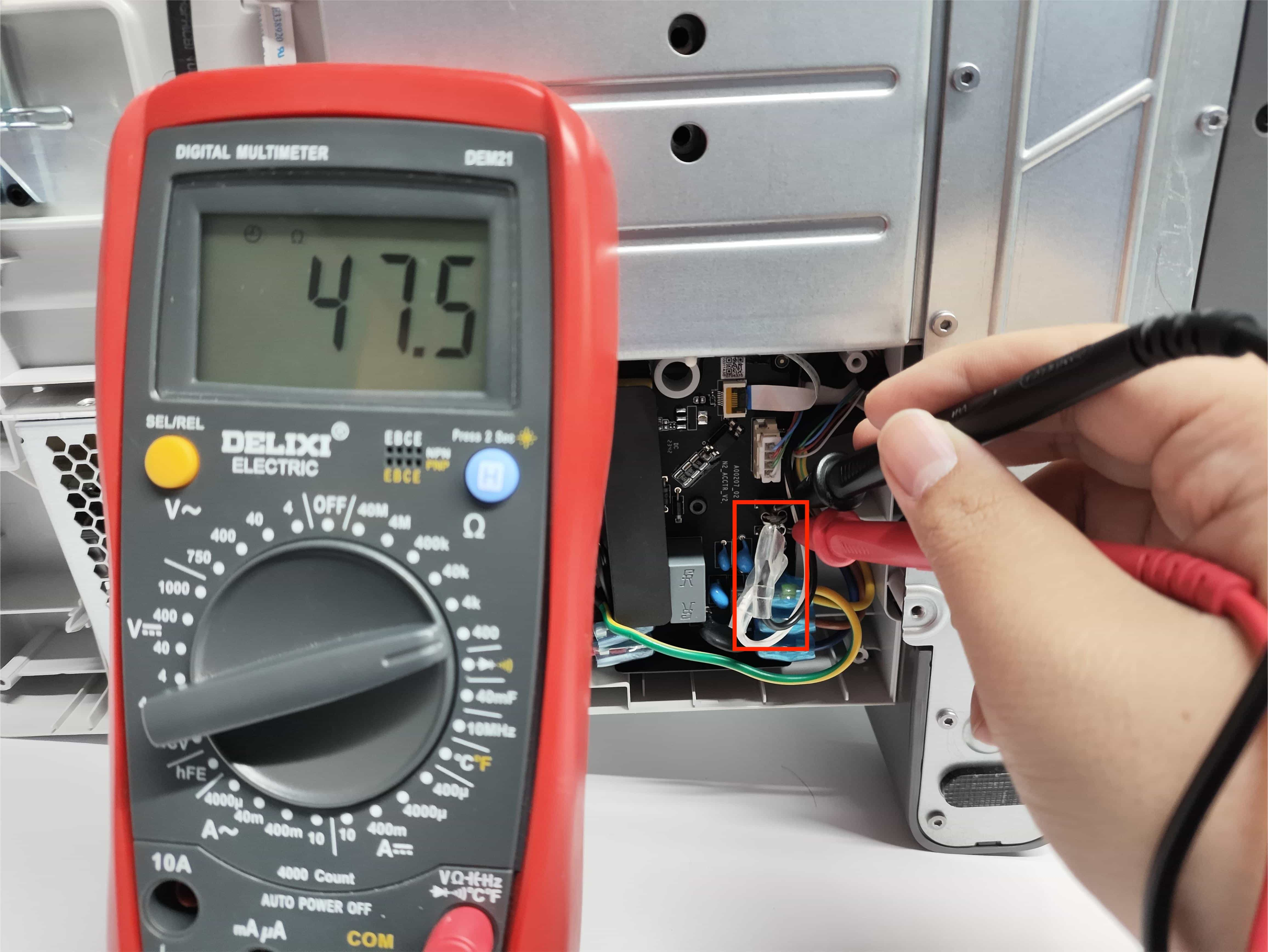 |
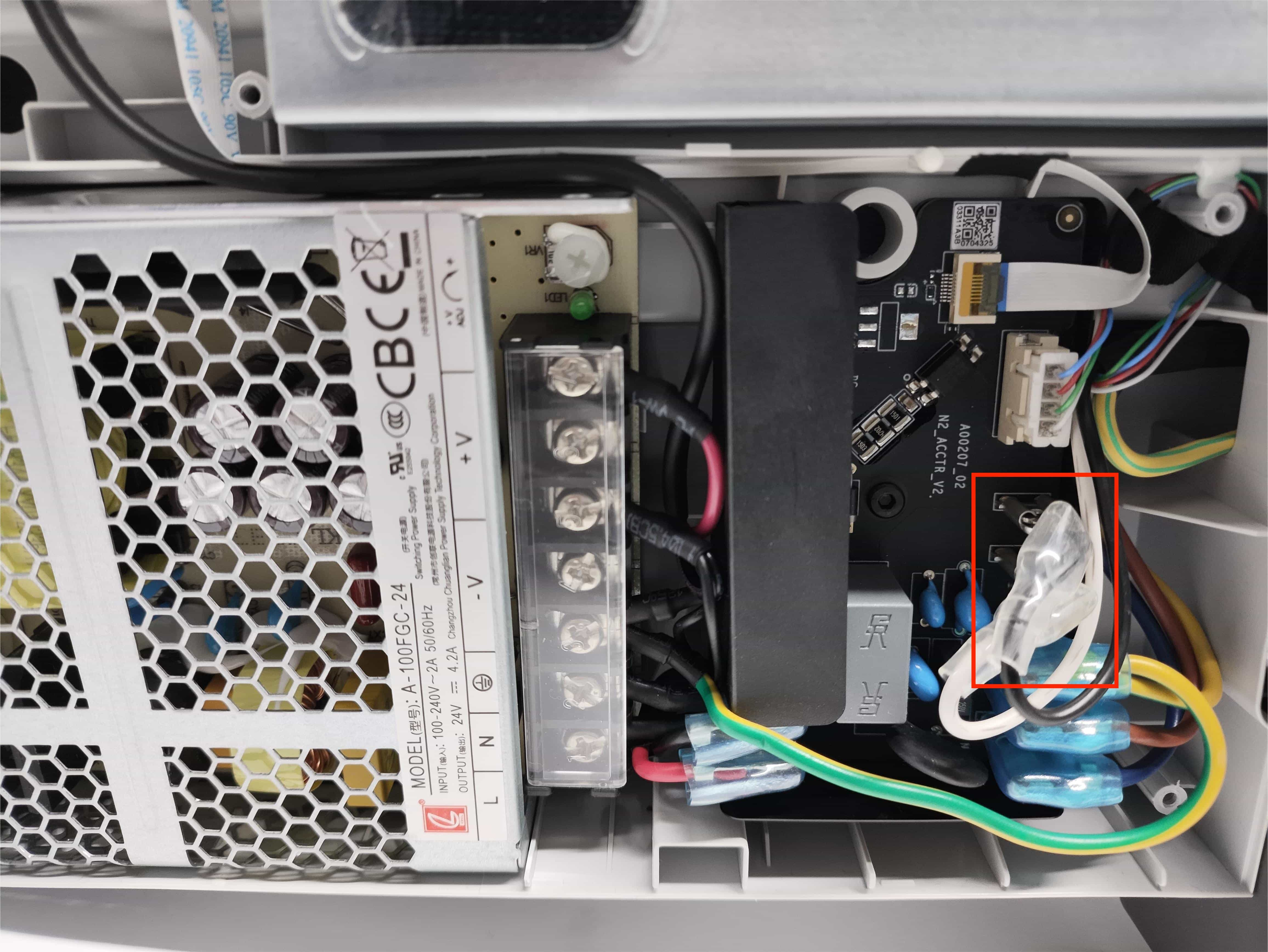
Important Note 1: The power connection location on the AC board is shown in the diagram. (This diagram is for reference purposes only to indicate the measurement points for heatbed resistance. It is not necessary to remove the components from the printer base during the measurement process)
Important Note 2: For convenience during measurement, you can use a tweezer to remove the insulation sleeve wrapped around the terminal block, as shown in the diagram. It is not necessary to remove the heating cables during measurement.
 The power connection location on the AC board |
 use a tweezer to remove the insulation sleeve wrapped around the terminal block |
¶ Step 4: Determine if the heatbed is malfunction
If both resistance values mentioned above are normal, the entire heatbed assembly (aluminum bed, heating cables, NTC sensor, and cable) functions properly.
In the case of abnormal heating or temperature issues with the heatbed, it is recommended to prioritize replacing the AC board.
However, replacing the heatbed assembly is necessary if both resistance values are abnormal.
¶ End Notes
We hope the detailed guide provided has been helpful and informative.
To ensure a safe and effective execution, if you have any concerns or questions about the process described in this article, we recommend submitting a technical ticket regarding your issue.
Please include a picture or video illustrating the problem, as well as any additional information related to your inquiry.