This page provides an introduction to the key components of the A1 3D printer, aiming to enhance your understanding of the printer's functionality.
¶ How does the A1 work?
The A1 3D printer is a machine that uses plastic filament to create 3D objects. It can transform digital models into physical objects. The working principle of the A1 typically involves the following steps:
¶ Creation or acquisition of a digital model
First, generate a 3D model or obtain an existing digital model using computer-aided design software, online resources, or other means.
¶ Slicing
Next, Bambu Studio slices the digital model into multiple thin layers. Each layer's information is converted into "G-code," a language understood by the printer. The G-code provides instructions to the printer regarding movement paths and speeds of the different axes during the printing process.
¶ Preparing the printer
Before initiating the printing process, the printer needs to be prepared. This involves loading the printing filament, positioning the build plate, and calibrating the printer's parameters to ensure optimal print quality.
¶ Printing
Once all preparations are complete, the A1 printer gradually constructs the object layer by layer on the print platform.
¶ The motion system of the A1
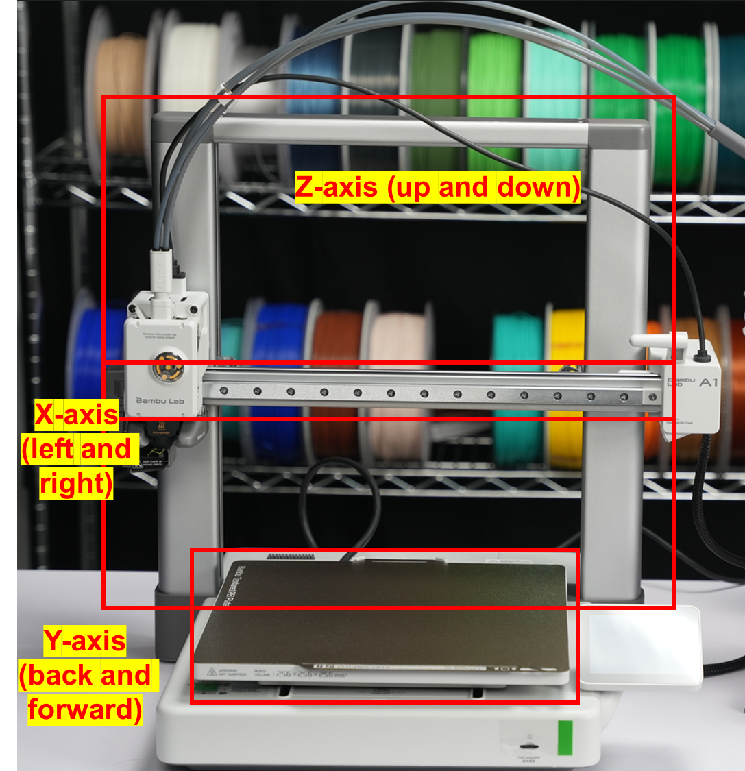
The A1 utilizes a Cartesian coordinate motion system, with a maximum print volume of 256 * 256 * 256 mm³. Its motion system includes the following components:
¶ X-axis motion
The X-axis motion system consists of a high-precision linear rail and a beam. The toolhead is mounted on a linear guide slider, allowing it to freely slide along the horizontal rail. By controlling the slider's left and right movement, the toolhead can achieve precise motion along the X-axis.
¶ Y-axis motion
The Y-axis motion system comprises a high-precision horizontal guide rail and a print bed. The print bed is mounted on a guide rail slider, enabling it to freely slide along the horizontal guide rail. By controlling the slider's forward and backward movement, the print bed can achieve precise motion along the Y-axis.
¶ Z-axis motion
The Z-axis motion system controls the vertical position of the toolhead relative to the print bed. It consists of dual optical shaft-linear bearing guide components, dual lead screws with nuts, stepper motors, and synchronous belt drive components. The dual lead screws are connected in series with the stepper motor through a synchronous belt, enabling synchronized motion of the two lead screws. Additionally, the synchronous belt is equipped with a quick tensioner and combined with a tension detection algorithm to ensure optimal tension range, ensuring precise and stable motion of the toolhead in the Z-axis direction.
By simultaneously controlling the movement of the X-axis, Y-axis, and Z-axis, the A1 can achieve precise motion of the toolhead in all three directions. Typically, these movements are controlled by motors and their corresponding drive circuits, with the machine controller reading the print file and sending instructions to control the motion path and speed of the print head.
¶ Toolhead module
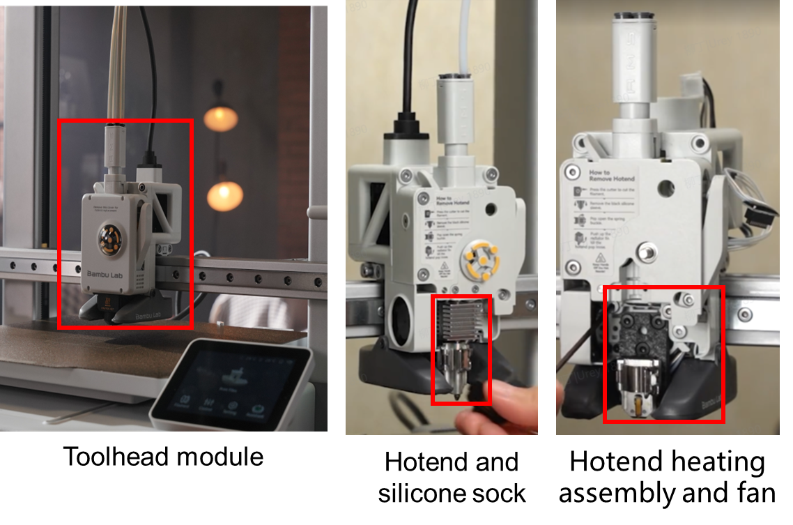
The toolhead unit is a crucial component of the A1. It comprises several key modules, including the hotend assembly, extruder unit, cutter unit, filament hub, and filament sensor.
¶ Hotend assembly
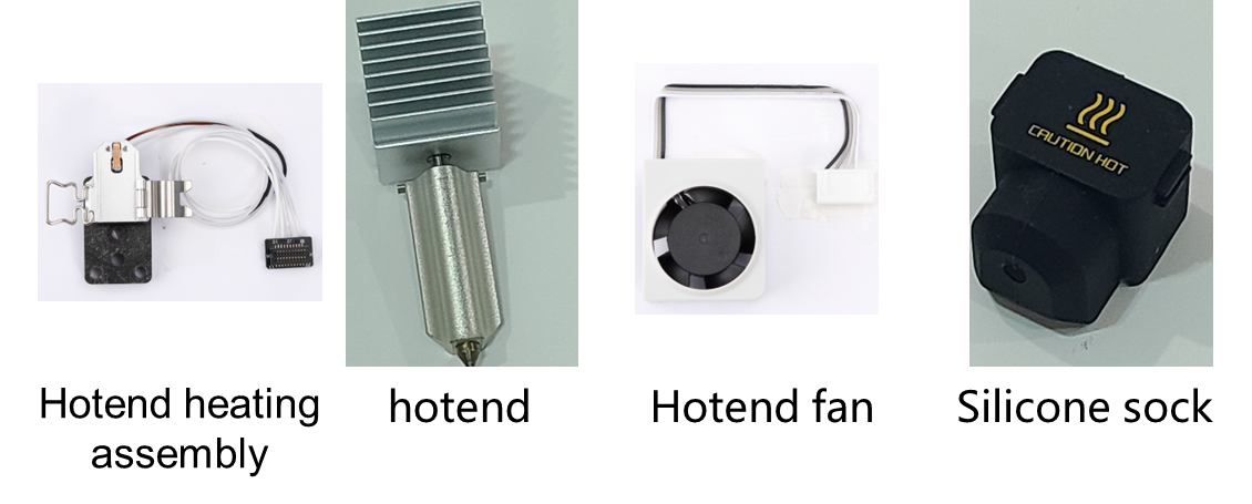
The hotend assembly is a core component of the toolhead module, consisting of a hotend heating assembly, a hotend (integrated with a nozzle and a heat sink), a hotend fan, and a silicone sock for hotend. The hotend assembly is responsible for heating the filament to a specific temperature, melting it, and depositing it in thin layers to generate the object.
Different filaments require different heating temperatures. For example, PLA is printed at lower temperatures around 210-220°C, while PETG requires higher temperatures around 250-260°C. Like the classic X1 series, the Bambu Lab A1 printer has an integrated hotend design that combines the nozzle and heat sink, enabling a faster heating effect than a regular hotend.
Additionally, it facilitates quick hotend replacement without unplugging tiny connectors or searching for a reliable screwdriver.
¶ Extruder unit
The extruder motor and extruder gears are essential components of the extruder unit. The extruder motor pulls the filament from the spool and feeds it into the hotend. Once heated and melted, the filament is extruded through the nozzle to create the printed model. The extruder motor is critical in accurately controlling the length of filament extruded through the hotend and is a core component of a 3D printer.
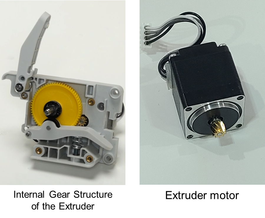
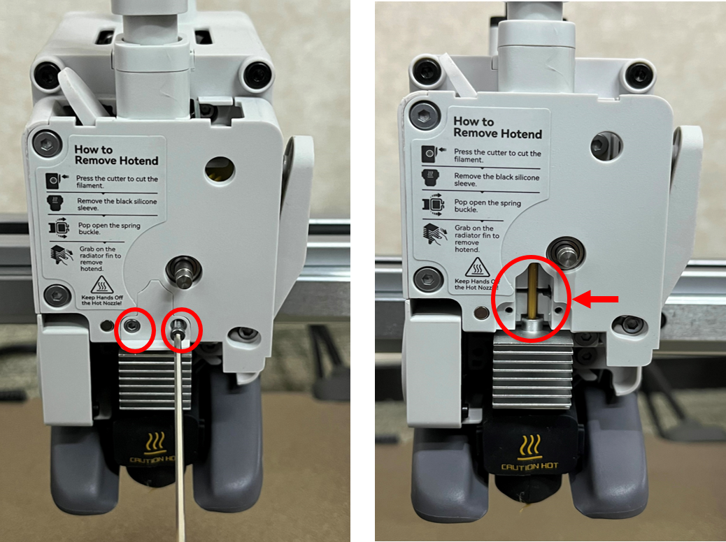
In the extruder unit, this small cover can be removed to observe the situation of filament clogging in the extruder gear.
The extruder gear can also be observed from the side by releasing the cutter lever. When filament powder accumulates in the extruder gear, this position can be used to clean the residue.
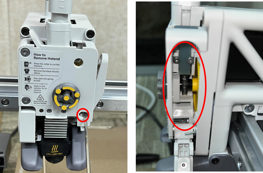
The filament hub can be carefully removed from the top (please be cautious when pulling the cable of the filament sensor), allowing observation from the top to check if the extruder gear is clogged.

¶ Cutter:
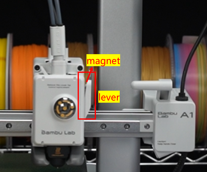
The cutter lever is installed on the toolhead to secure the cutter blade and the magnet for position detection. The lever is driven to cut through the filament during the cutting process by pressing the handle. After cutting, the cutter lever automatically rebounds.
The lever has a magnet, and a corresponding filament sensor is inside the toolhead at the same horizontal position as the magnet. Therefore, the printer can sense the position of the cutter lever through the filament sensor.
¶ Filament hub and filament sensor
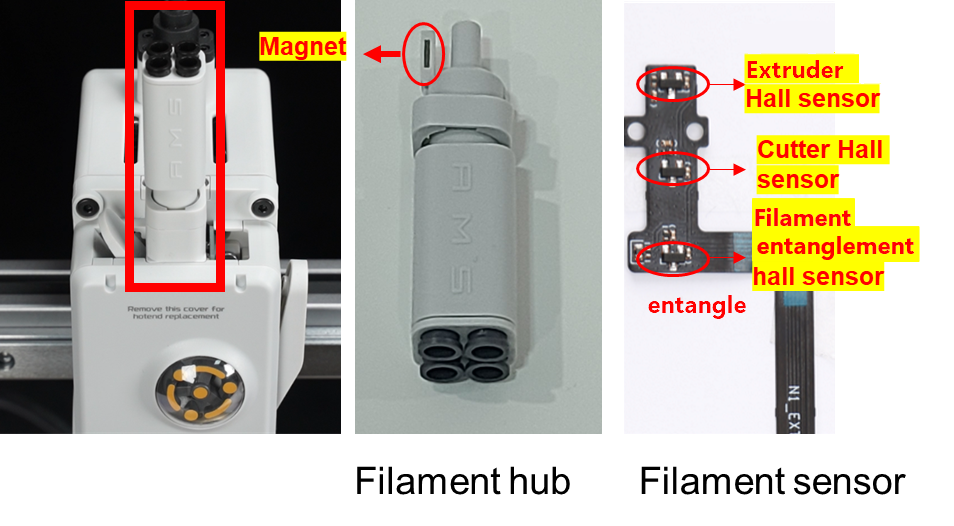
The PTFE tubes are connected to the filament hub on the toolhead. This allows the toolhead to accommodate four different filaments, enabling multi-color printing combined with a multi-color printing module. In addition, the filament hub contains a magnet inside, which works in conjunction with a filament entanglement hall sensor to check for filament entanglement. When there is excessive resistance during filament feeding, the filament hub is pulled down, causing the magnet to move closer to the filament sensor and triggering a filament entanglement alert.
The filament sensor board includes circuits for filament feeding detection, filament cutting detection, and filament entanglement detection. The filament feeding detection is used to check if the filament is present in the extruder, the filament cutting detection controls the cutting action, and the filament entanglement detection is used to check for filament entanglement.
¶ Cooling System
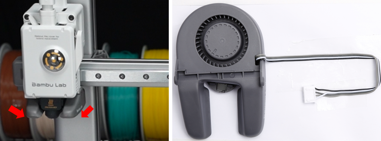
Efficient cooling of the printed model is essential for fast printing. The A1 has a custom 5015 centrifugal fan, featuring two opposing air outlets. This design directs the cooling air precisely towards the vicinity of the nozzle, ensuring rapid cooling of the printed parts.
¶ Heatbed unit
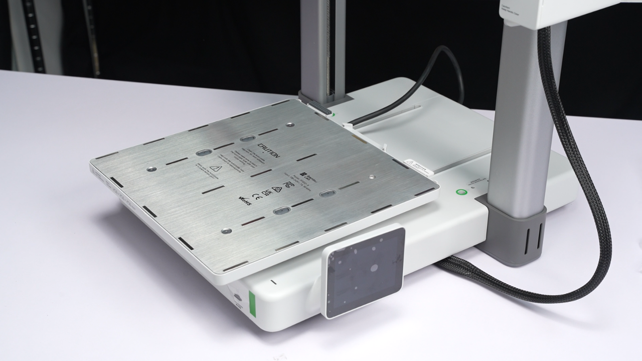
The main function of the heatbed is to heat the printing surface to help the printed layers adhere better to the build plate. Without heating the print surface, the first layer of material deposited on the heatbed may not adhere stably, leading to warping or even detachment of the printed object during subsequent printing processes. In the case of the A1 printer, the heating temperature of the bed is controlled based on the type of printing material being used and can reach a maximum of 100°C.
Additionally, the heatbed serves as the Y-axis motion component of the printer. The Y-axis motor is connected to the heatbed through a synchronous belt, driving the heatbed to move along the Y-axis and enabling printing in the Y-direction. The X-axis movement is accomplished by the X-axis motor driving the tool head through a synchronous belt. The coordinated movement of the two axes allows the printer nozzle to achieve movement in the XY direction on the heatbed surface.
¶ Purge wiper and nozzle wiper
¶ Purge wiper
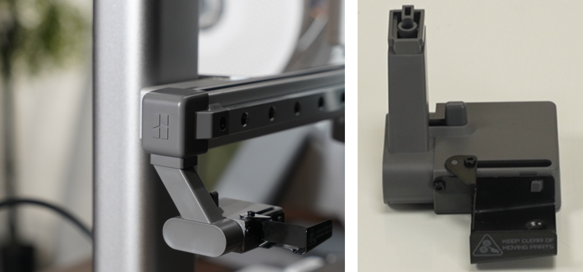
The purge wiper is specifically designed to handle the waste filament discharged from the nozzle efficiently. Its functions include collecting and conveying the waste filament and ensuring proper disposal to maintain continuous and smooth printing operations. This device plays a crucial role in various stages of the printing process, including printer setup, pause and resume printing, filament loading, and unloading, as well as filament switching and purging during multi-color printing.
¶ Nozzle wiper
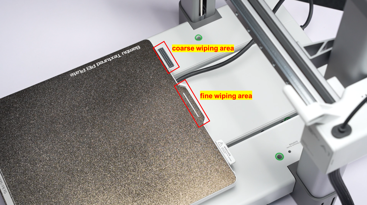
The wiper assembly cleans the nozzle before starting a printing task. After each print job is initiated, cleaning is automatically performed without manual intervention. The cleaning action includes a coarse wipe and a fine wipe. The coarse wipe is primarily used to clean any residual waste material on the hot nozzle, while the fine wipe is performed to clean the nozzle tip for a smooth finish.
The A1 printer comes pre-installed with a set of silicone wiper components on the heated bed for the coarse wiping operation. It's important to note that replacing the silicone wiper components is part of routine maintenance. If the silicone wiper components are damaged, you can purchase replacement parts from the official store.
The fine wiping action refers to the nozzle moving down 1~2 millimeter at a specific position on the build plate. Therefore, if you notice some wear on the coating in that area of the build plate, there's no need to worry as it is normal.
¶ Build plate
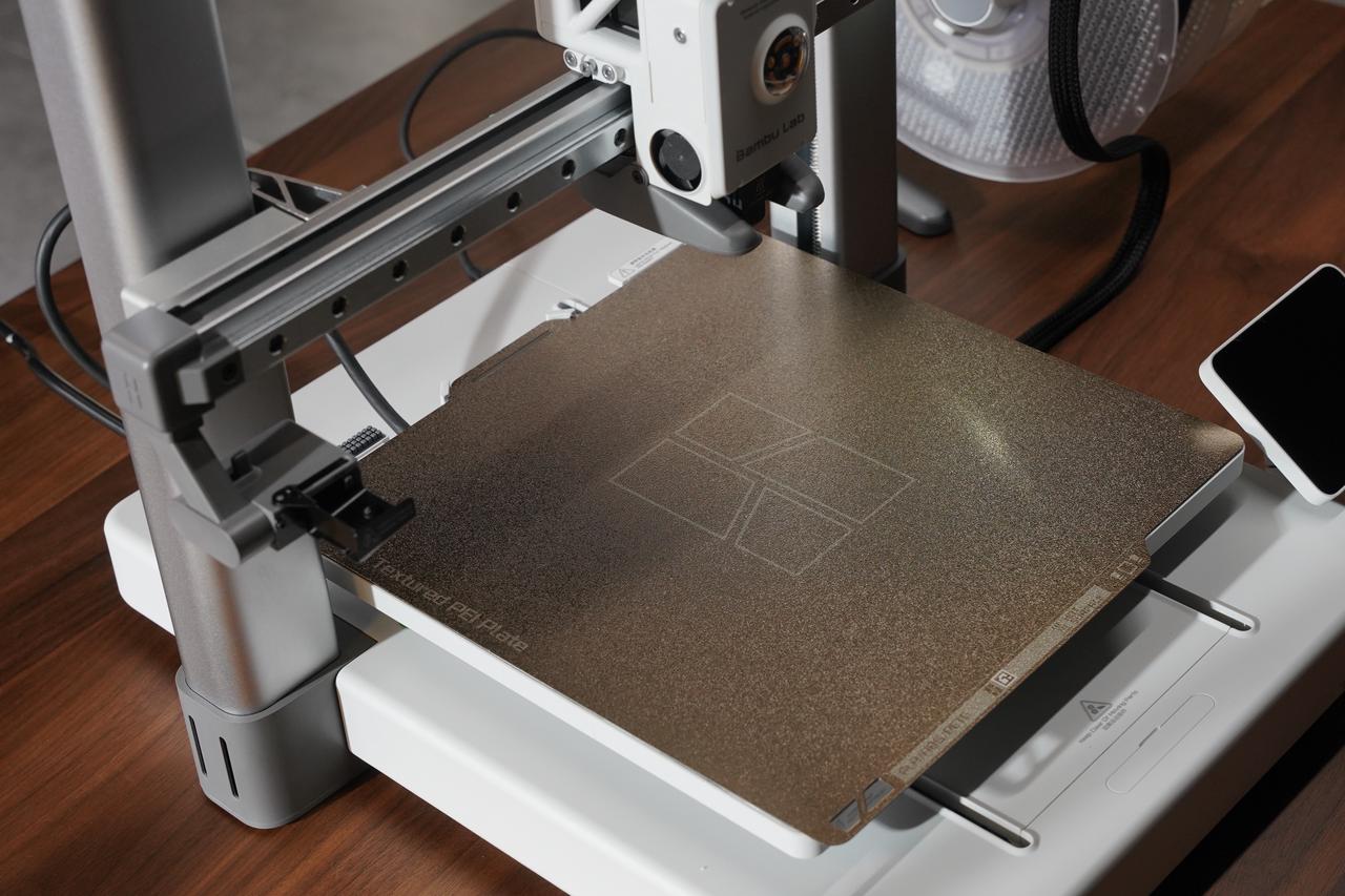
The A1 comes with a textured PEI plate (included in the unboxing package) that is formed by spraying PEI material onto a stainless steel plate. It provides a special textured surface for the bottom of printed objects. This print bed is suitable for printing various materials, such as PLA, PETG, TPU, and more, without the need for any adhesive. After printing, waiting for the build plate to cool down before removing the printed object is recommended. It is advised to clean the build plate regularly to maintain optimal adhesion. Additionally, it is recommended to minimize direct contact of fingers with the build plate surface to prevent skin oils from affecting the adhesion of materials to the build plate.
¶ Belt Tensioner
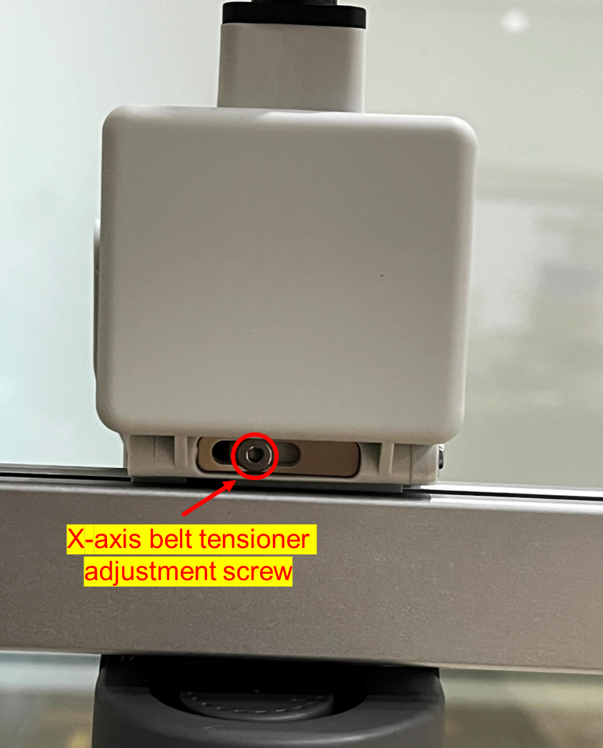
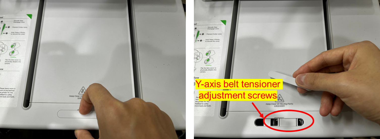
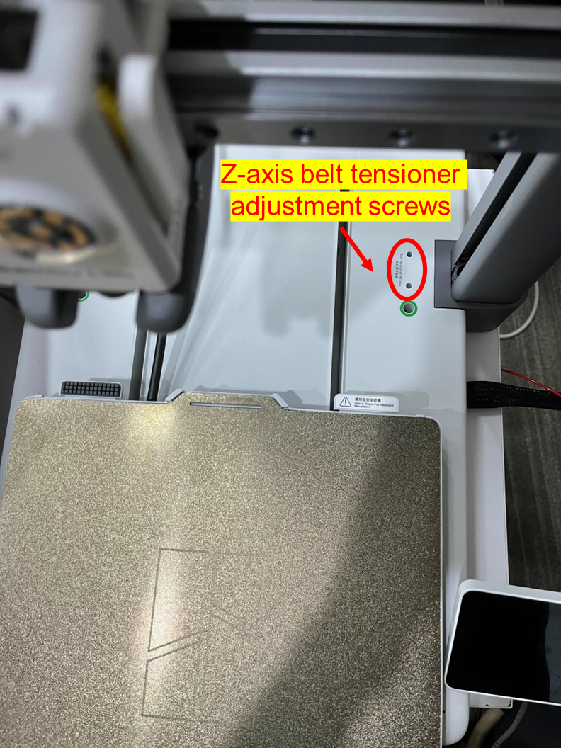
The A1 is equipped with 3 adjustable belt tensioners. The Belt Tension Monitor (BTM) will monitor the tension of the belts and provide feedback to you. You can adjust the belt tension based on the feedback to achieve optimal performance. (Please refer to A1 Belt Tensioning).
¶ X-axis Belt Tensioner
¶ Y-axis Belt Tensioner
¶ Z-axis Belt Tensioner
¶ Electrical Components
The A1 incorporates various electronic components, and here is a brief overview of some of the most important components and their functions:
¶ Circuit board
The main control board of the A1 printer consists of a low-power SoC (System-on-Chip) with a dual-core processor, Wi-Fi baseband, Bluetooth baseband, RF module, and other peripherals. It also includes a dual-core MCU (Microcontroller Unit) and a single-core MCU. Additionally, it incorporates stepper motor drivers and connectors required for connecting various electronic devices to the printer.
The SoC is primarily responsible for handling the user interface of the A1 printer and managing the connection between the slicing software/mobile application and the printer. On the other hand, the MCU controls the printer's heating and movement after receiving the CPU's G-code stream.
¶ Camera
The printer integrates a camera that can be used for real-time monitoring of prints using the Bambu Slicer or Bambu Handy applications. It can also be utilized for print defect detection (supported after firmware updates).
In addition to its monitoring capabilities, the camera can record printed videos and create time-lapse videos. While the machine does not have night vision, the camera module has an LED that can illuminate the printed object.
¶ A1 Control Module Functions
¶ A1 Auto Bed Leveling
The auto bed leveling process for the A1 printer involves the following steps:
¶ Touch Probe Detection
The hot end of the A1 printer is equipped with extruder head force sensing capability, which allows for detecting the contact between the extruder nozzle and the heated bed. When combined with the Z-axis movement, it enables direct measurement of the relative height of a specific point on the heated bed with respect to the center of the bed.
¶ Height Mapping
By probing the hotbed through nozzle contact, A1 performs height measurements on 49 points arranged in a 7x7 grid on the hotbed, thus obtaining a height map of the hotbed. This height map records the height of each point on the 7x7 XY coordinate grid.
¶ Compensation Adjustment
During printing, the printer automatically adjusts the height of the Z-axis at different XY coordinates based on the height map. This ensures a constant distance between the nozzle and the hotbed, allowing the printed material to adhere uniformly to the print bed.
With the auto-leveling function, A1 can automatically detect and adjust the height of the print bed before printing and during the printing process. This improves print quality and accuracy by avoiding adhesion issues caused by an uneven print bed surface. It enhances the success rate and consistency of prints.
¶ A1 Resonance Compensation
Resonance compensation aims to alleviate or eliminate instability and quality issues caused by mechanical vibrations or resonances during printing.
During the operation of a 3D printer, each acceleration and deceleration excites the printer's inherent resonance modes, leading to subtle back-and-forth vibrations. These vibrations, such as surface ripples, vibration marks, or distortions, can negatively affect print quality.
To mitigate these resonance effects, A1 employs resonance compensation technology, which involves the following steps:
¶ Vibration Analysis
By utilizing an accelerometer, such as an X-axis accelerometer or a heatbed accelerometer (Y-axis), the printer can induce vibrations in the motors at different frequencies and capture the actual vibration curves of the XY axes. These curves can then be analyzed to identify the resonance modes of the XY axes.
¶ Compensation Parameter Calculation
Based on the analysis of resonance modes, the printer system will use specific compensation algorithms to calculate compensation parameters.
¶ Dynamic Adjustment
During the printing process, the resonance compensation feature can apply a compensation amount to the motion controller based on real-time motion control commands, effectively canceling out resonance modes and ensuring that the movement of the extruder nozzle aligns with the expected G-code.
By utilizing resonance compensation technology, A1 can reduce the impact of mechanical vibrations and resonances during printing, thereby enhancing print quality and accuracy. It helps minimize surface ripples, vibration marks, or distortions on printed parts, resulting in smoother and more precise print outcomes. This is particularly important for applications that require high precision and stability.
¶ Flow Dynamics Calibration
During the 3D printing process, accurately controlling material flow is crucial for print quality. Incorrect flow settings can result in issues such as inaccurate part dimensions, poor interlayer adhesion, and surface quality problems. The purpose of dynamic flow calibration is to measure the dynamic response characteristics of the material at different flow rates, calculate the material's hysteresis during the extrusion process, and perform real-time hysteresis compensation during printing. This allows the printer to achieve uniform extrusion even at high speeds and accelerations, providing more accurate and consistent print results.
Implementing dynamic flow calibration typically involves the following steps:
¶ Dynamic Hysteresis Measurement
The A1 utilizes sensors to measure the flow rate variation of the material during the calibration process.
¶ Dynamic Flow Calibration
The printer automatically calculates compensation parameters using the flow rate variation data, similar to "pressure advance" in Klipper or "linear advance" in Marlin.
¶ Real-time Adjustment
During the printing process, the printer compensates for the extrusion volume based on real-time flow rate requests, ensuring that the material flow from the extruder remains synchronized with the high-speed motion of the XY axes. This ensures consistent flow rates across different printing areas and layers.
Through dynamic flow calibration, the A1 can dynamically adjust the material flow during printing to adapt to different printing conditions and requirements. This helps improve print quality, accuracy, and consistency, ensuring that printed parts have correct dimensions and quality while reducing issues caused by inaccurate material flow.
¶ Active Motor Noise Canceling
Motor noise is typically caused by mechanical vibrations, motor driving, fan operation, or extruder movement in a 3D printer. These noises can not only be disruptive to the operator but also affect the comfort of the surrounding environment. The motor noise suppression function aims to reduce the overall printing noise by suppressing the noise generated by the motors during the printing process.
Motor noise reduction is achieved by measuring the undesirable characteristics within the motor and calculating the compensation amount in real-time based on the motor's current operating state during printing. This compensation is then applied to the motor, generating reverse vibrations within the motor to counteract the vibrations caused by the motor's imperfections. Motor noise calibration is available in the calibration menu, allowing users to recalibrate the motor noise as needed.