¶ Applicable models
Bambu Lab A1.
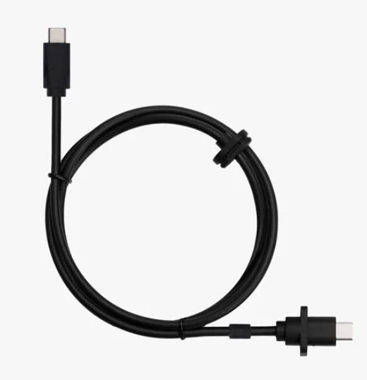
¶ USB-C cable
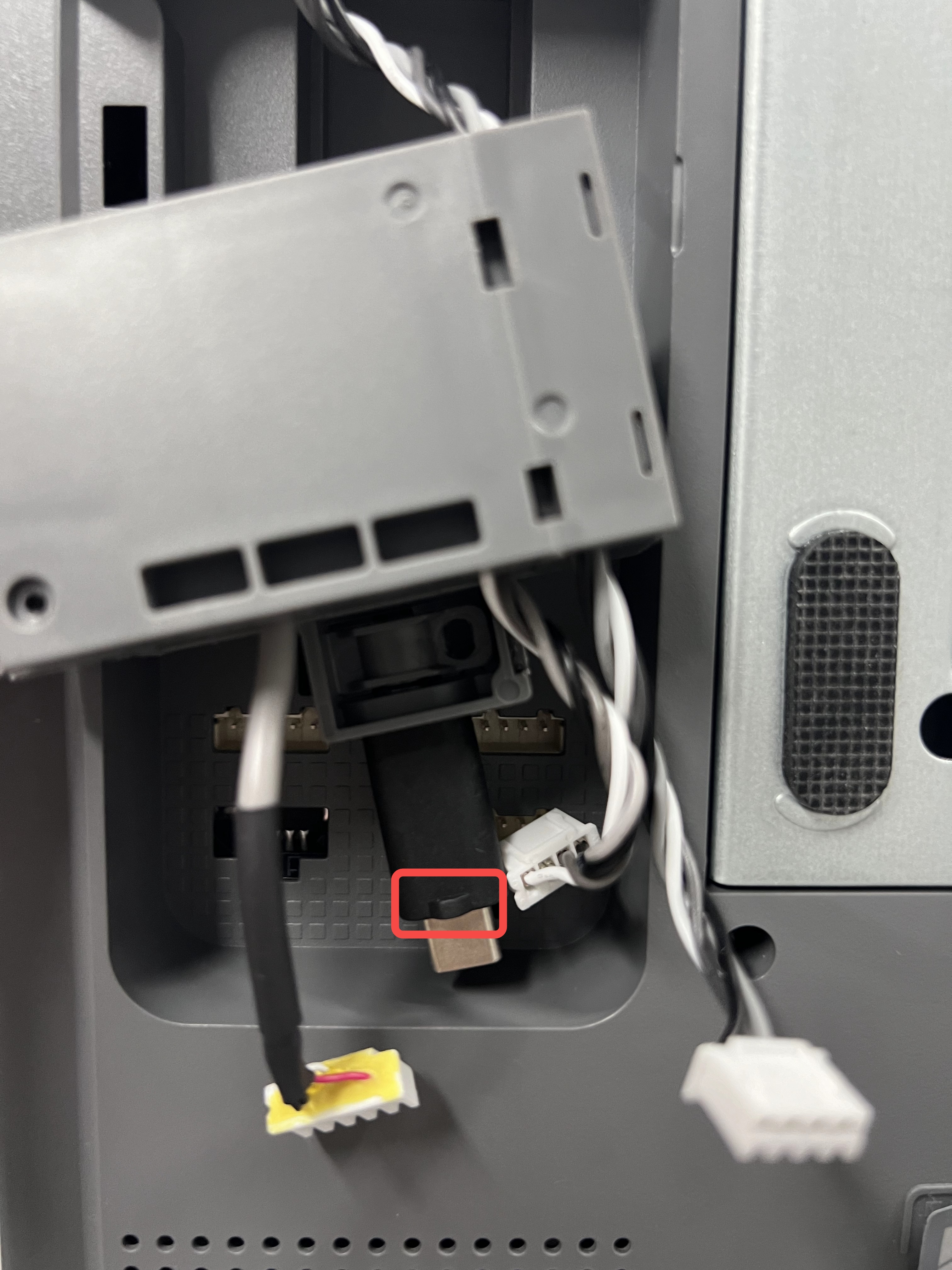
The USB-C cable connects the mainboard and the TH board.
¶ When to use
- The USB-C cable is broken.
- The printer cannot detect the toolhead.
- Recommended by Bambu Lab Support.
¶ Safety Warning
IMPORTANT!
It's crucial to power off the printer before conducting any maintenance work, including work on the printer's electronics and tool head wires. Performing tasks with the printer on can result in a short circuit, leading to electronic damage and safety hazards.
During maintenance or troubleshooting, you may need to disassemble parts, including the hotend. This exposes wires and electrical components that could short circuit if they contact each other, other metal, or electronic components while the printer is still on. This can result in damage to the printer's electronics and additional issues.
Therefore, it's crucial to turn off the printer and disconnect it from the power source before conducting any maintenance. This prevents short circuits or damage to the printer's electronics, ensuring safe and effective maintenance. For any concerns or questions about following this guide, open a new ticket in our support page and we will do our best to respond promptly and provide the assistance you need.
¶ Tools and material needed
- A new USB-C cable
- H2.0 hex wrench
- H1.5 hex wrench
- 20 minutes
¶ Remove the old USB-C cable
¶ Remove the USB-C cable from the toolhead
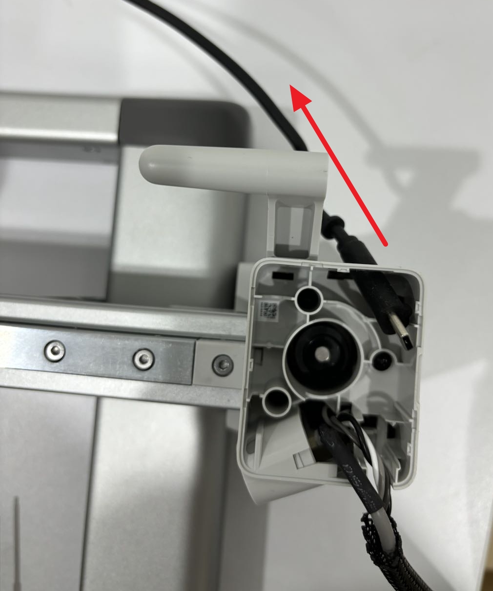
Remove the four screws fixing the USB-C cable to the toolhead, and then pull it upwards to remove it.

¶ Remove the front cover of the X motor box and the wire attachment
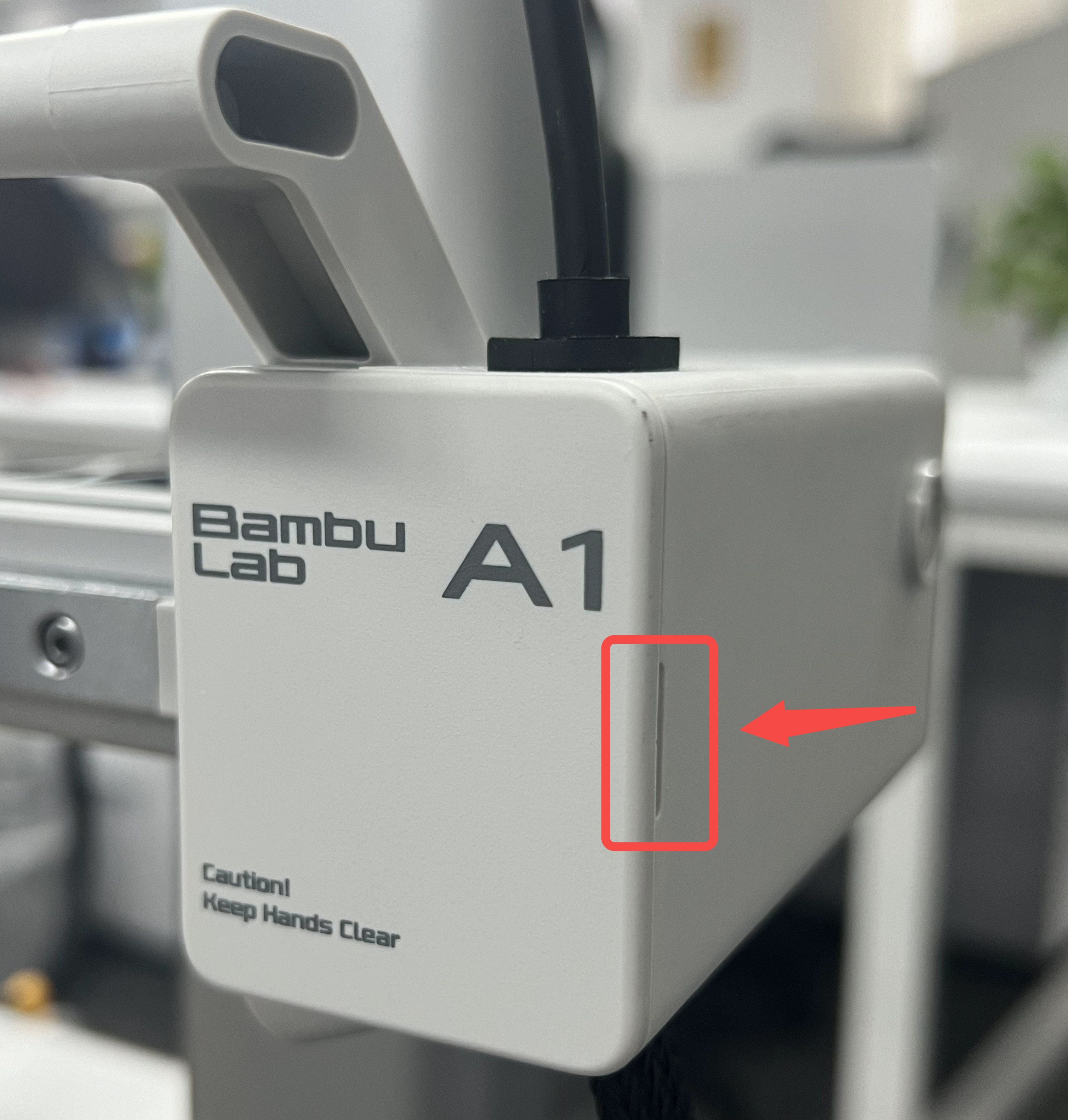
Step 1. Pry on the lower-right corner of the front cover to remove it.
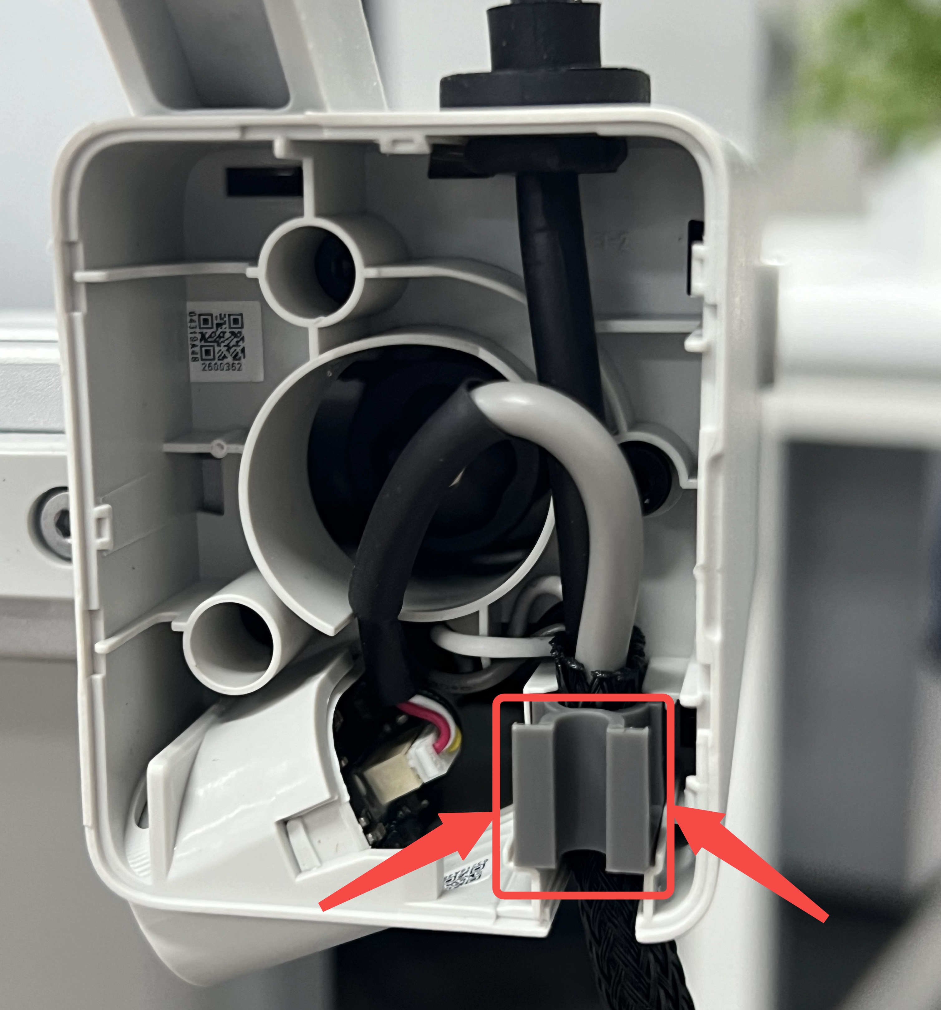
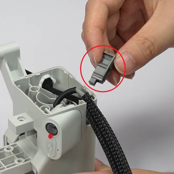
Step 2. Press both sides of the wire attachment with your hands and remove it.
¶ Remove the USB-C cable fixture
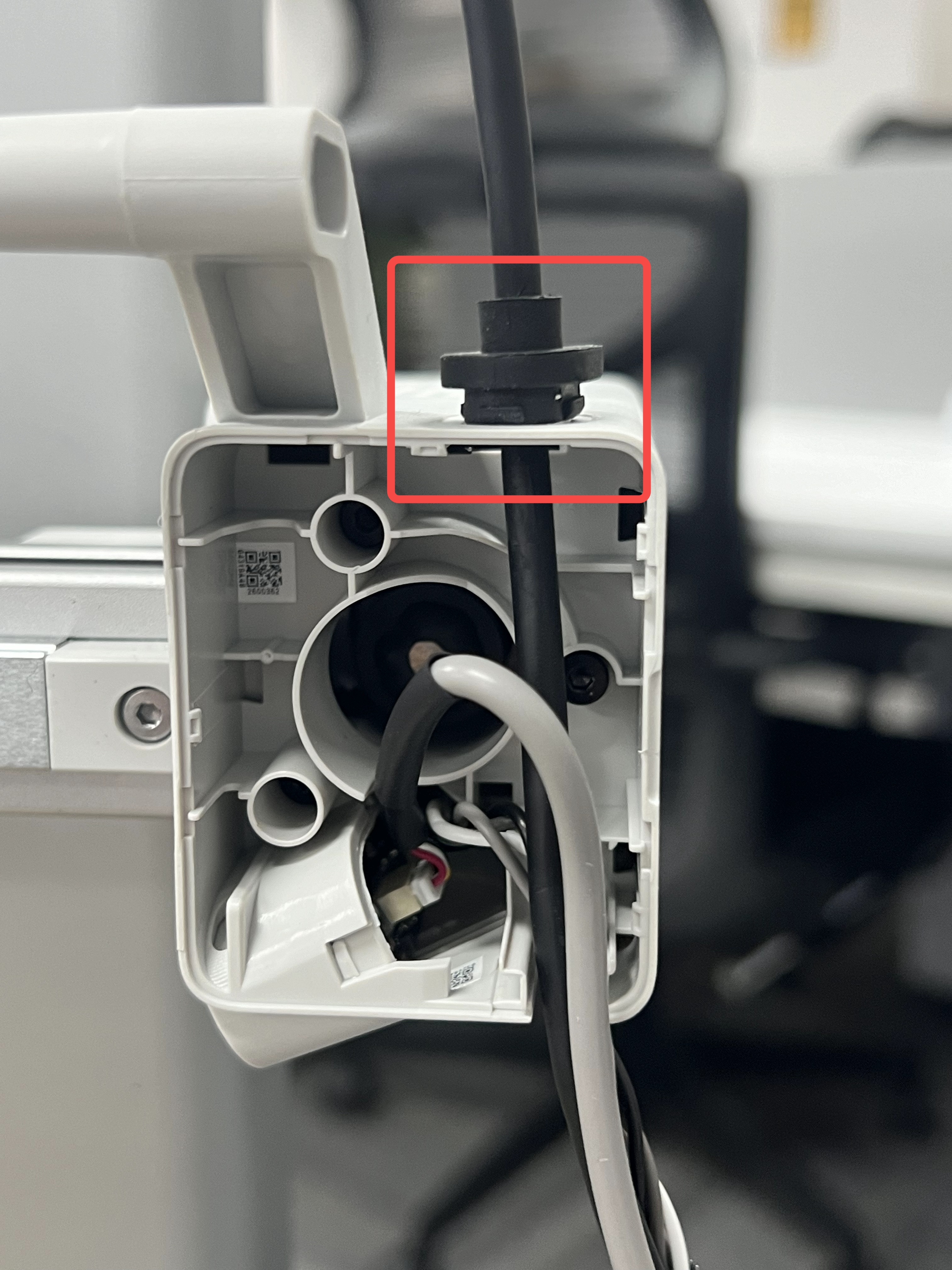
Use a flat screw or similar tool, pry on a side of the fixer on top of the X motor box to remove the fixture.
¶ Remove the cable box
-
For easy access to the bottom section of the A1, you need to place the printer on the front. Start by flipping the screen on its side, then gently place the printer on its front, as shown in the image below. Use a box of filament to keep the top side raised to avoid putting pressure on the extruder and the screen.
-
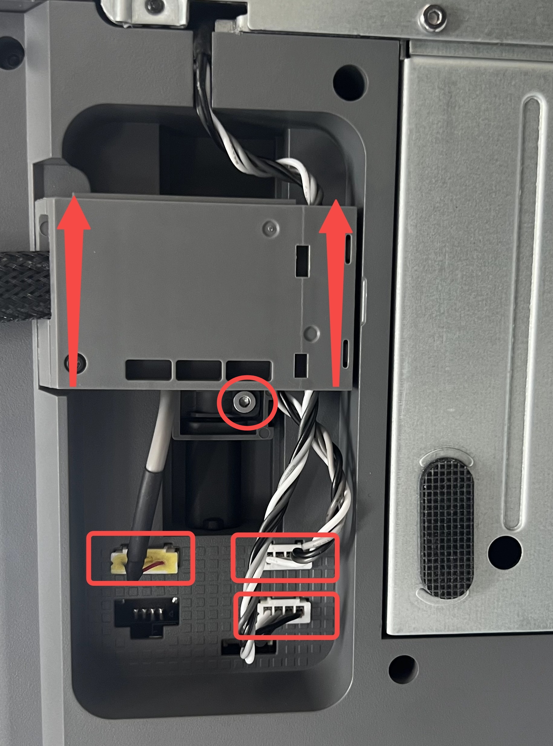
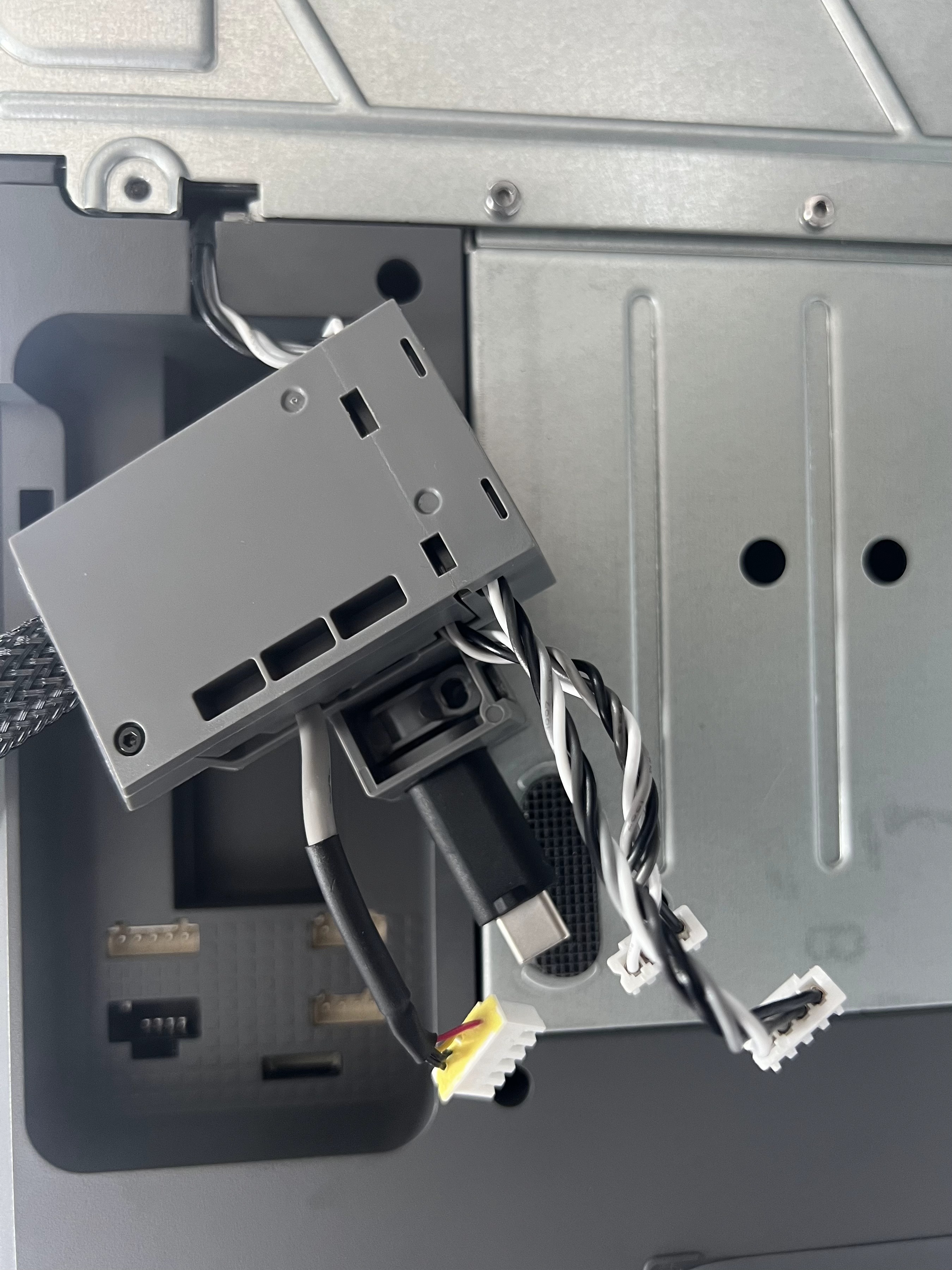
Disconnect the cables of the camera, X-axis motor, and Z-axis motor; Loosen 1 screw; Push the cable bracket upwards, disconnect the USB data cable, and remove the cable bracket.
 |
 |
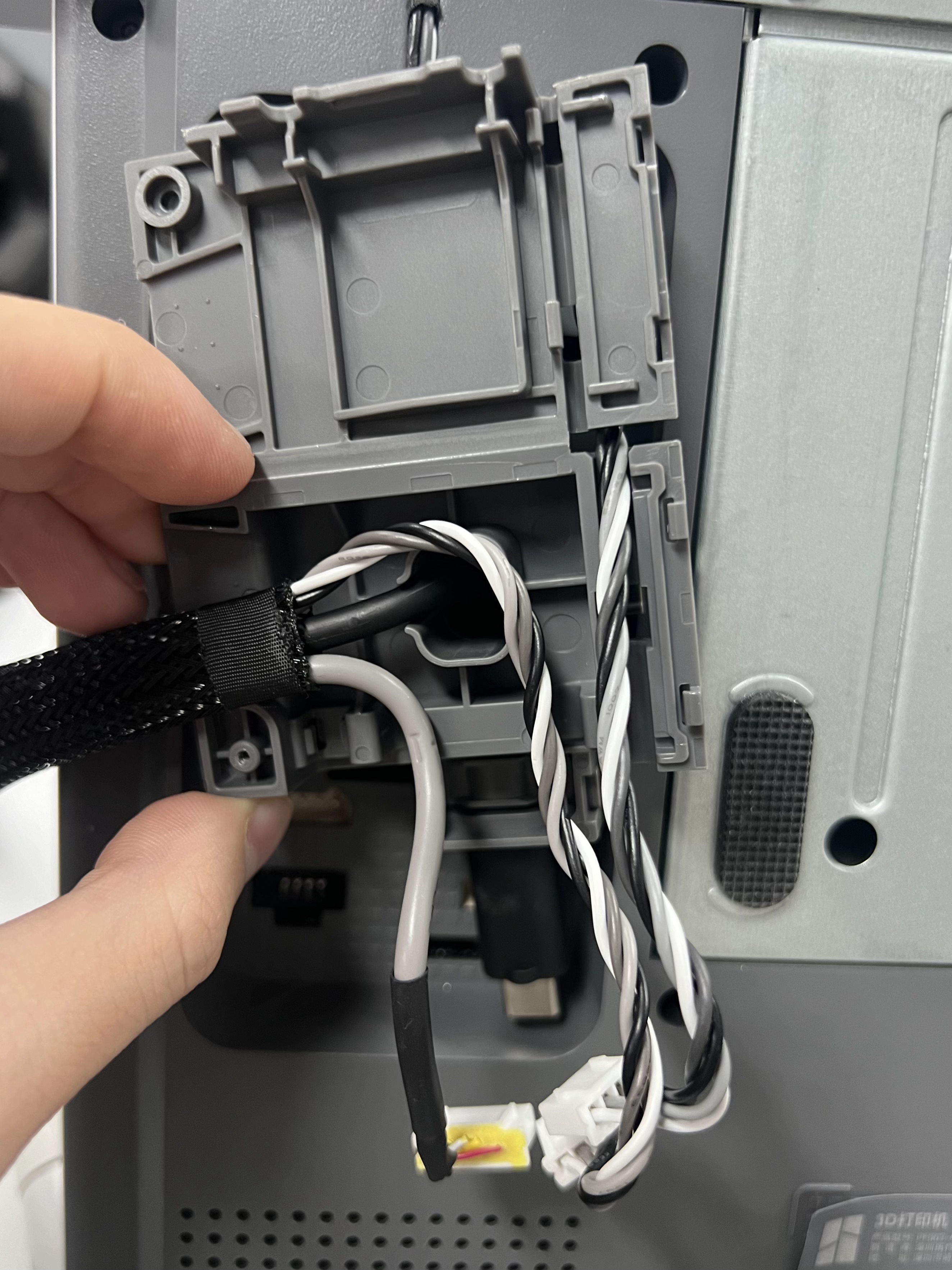
¶ Take out the USB-C cable from the cable box
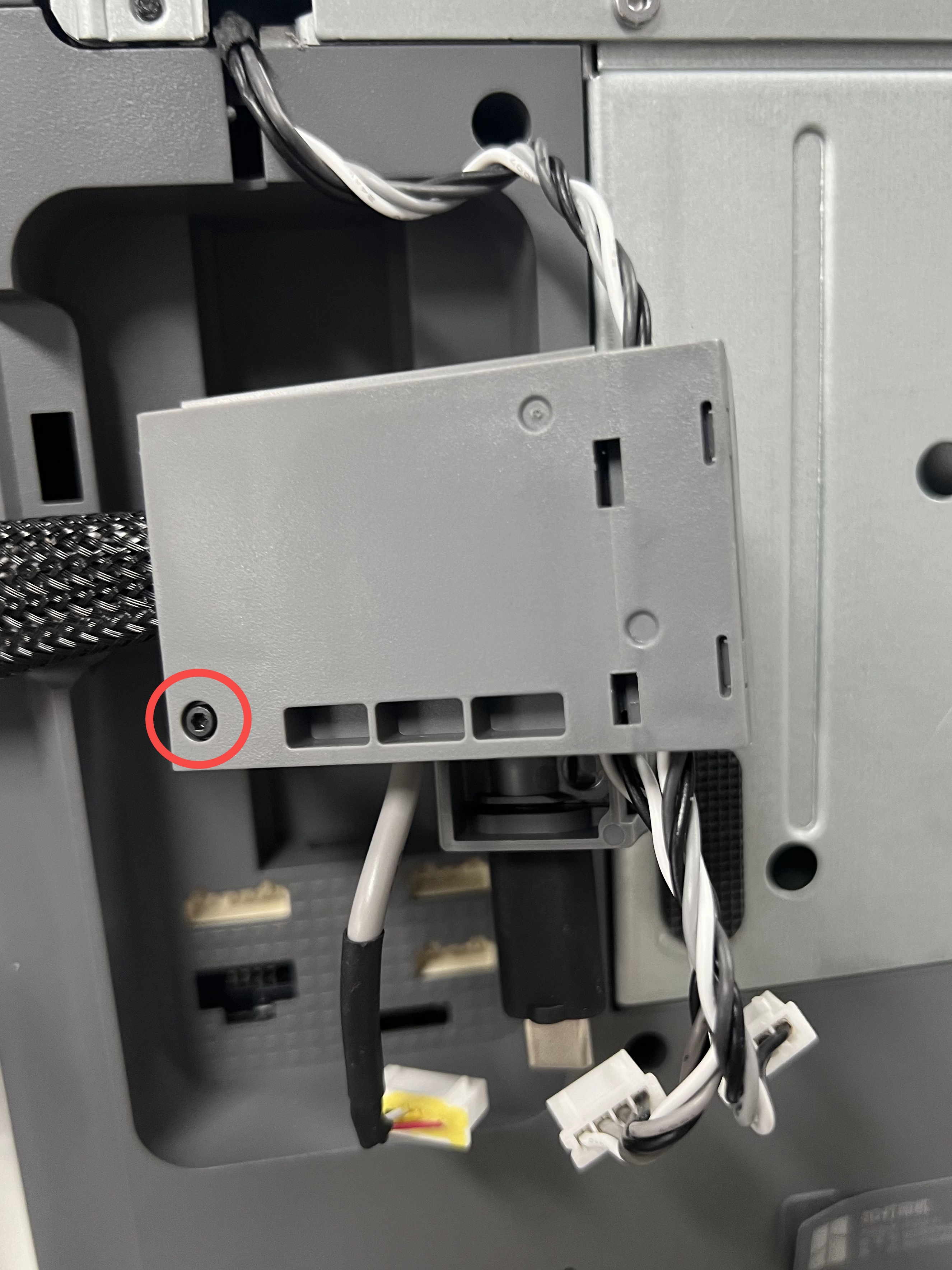
Step 1. Loosen the screw and open the cover.
 |
 |
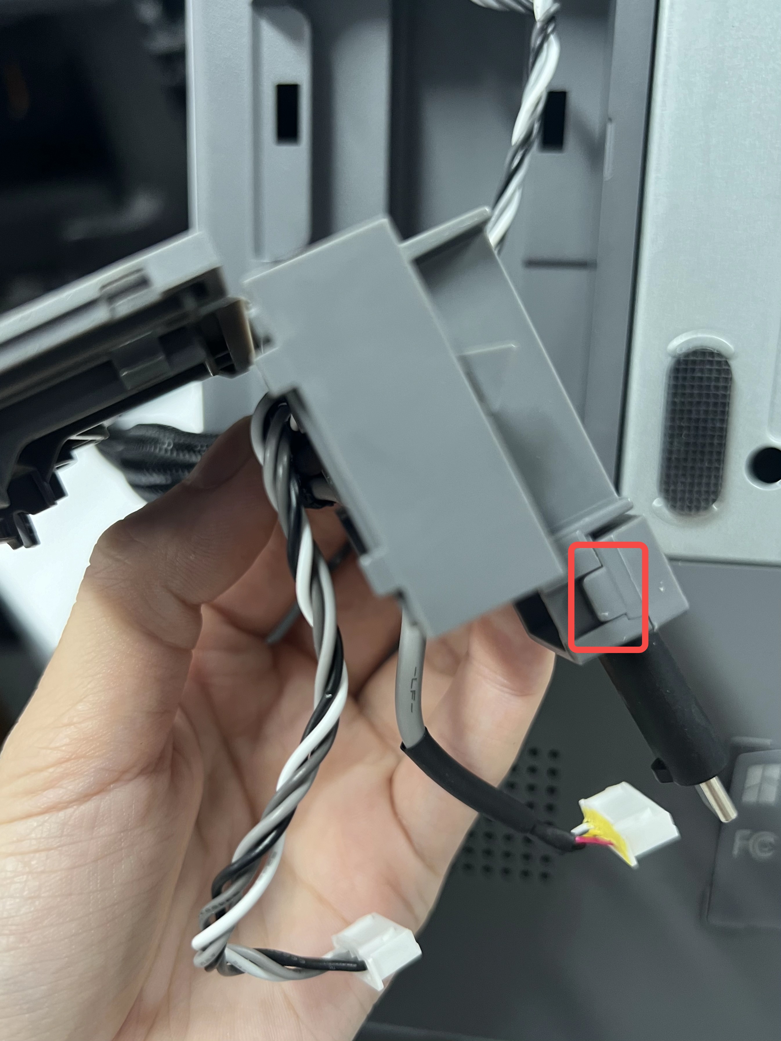
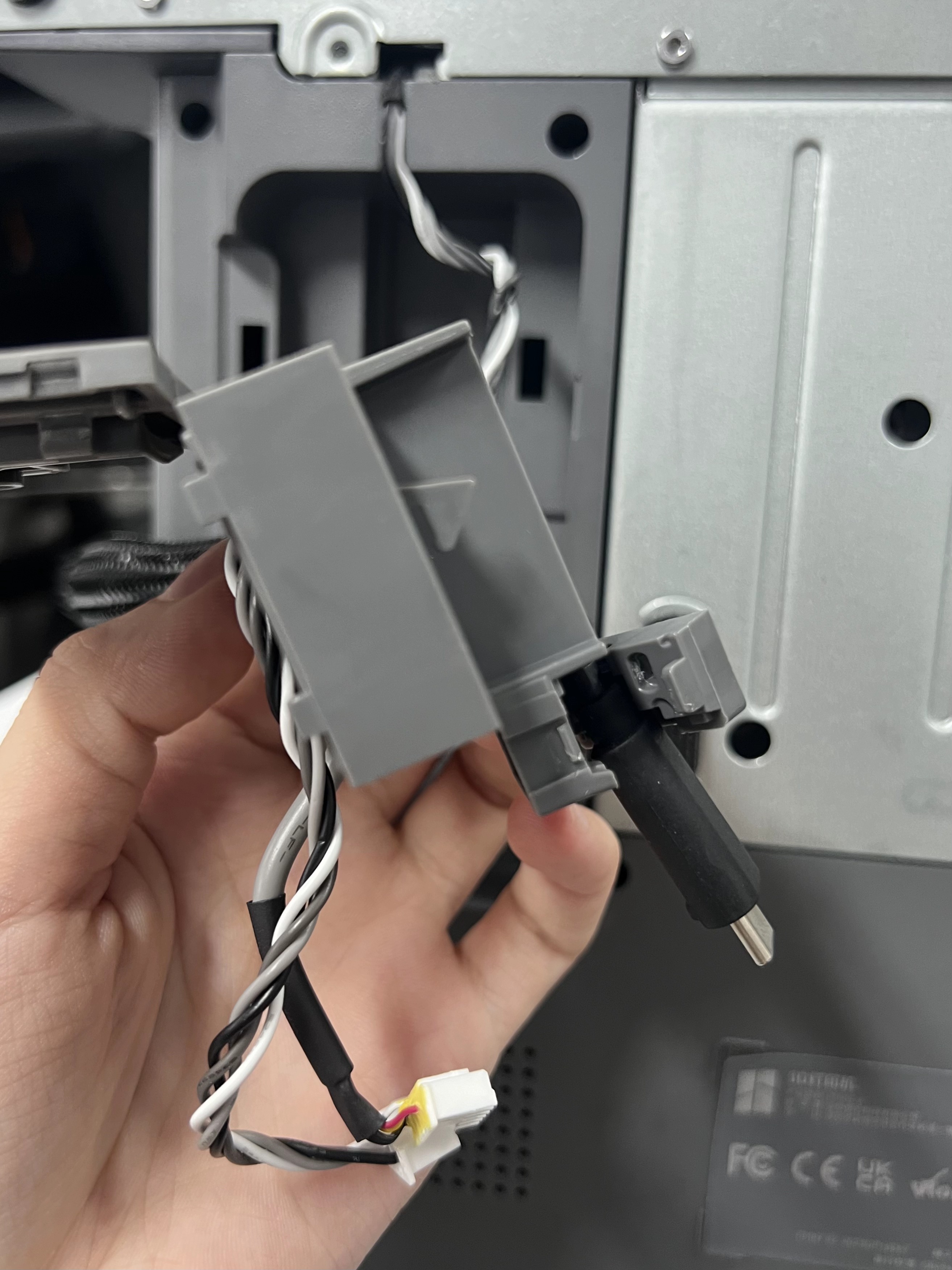
Step 2. Open the USB-C bracket, and take out the USB-C cable.
 |
 |
¶ Take out the USB-C cable from the metal sleeve
Step 1. Tear away the tape on the metal sleeve.
You can stick the tape on the printer or table for later use.
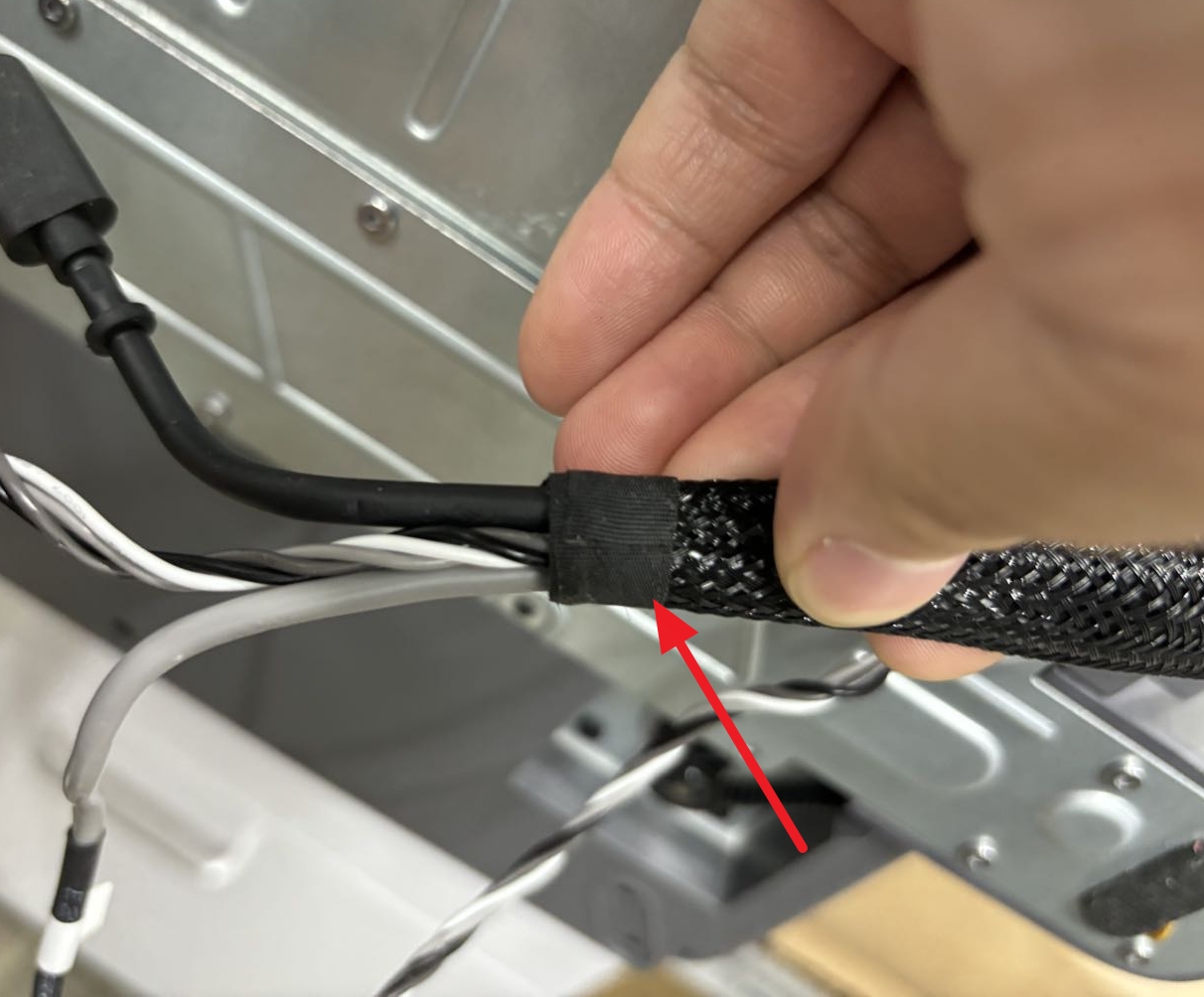
Step 2. Firstly, take out the end of the USB-C cable the with ferrite core attachment. Remove the attachment from the two buckles.
Please remember the location of the ferrite core attachment on the USB-C cable. You need to install it to the new cable in the same location.
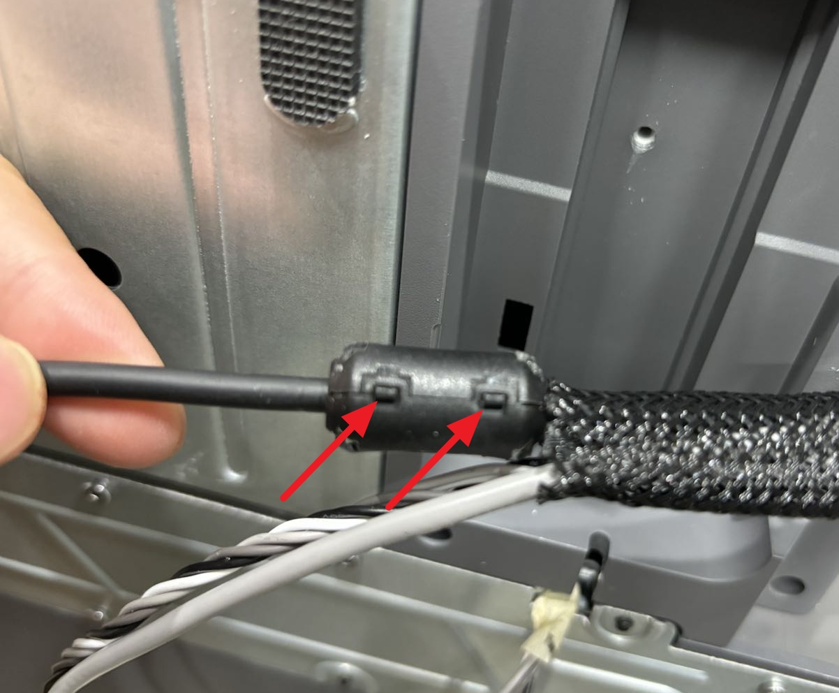
Step 3. Take out the USB-C cable from the metal sleeve.
¶ Remove the USB-C cable
Remove the USB-C cable from the X motor box.
¶ Install the new USB-C cable
¶ Install the USB-C cable to the X motor box
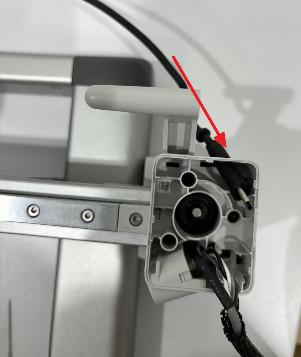
Take off the ferrite core attachment on the cable, and then guide the cable through the small hole above the X motor box.
We recommend that you mark the location of the ferrite core attachment so that you can install the it back easily later.
¶ Put the USB-C cable in the metal sleeve
Step 1. Push the USB-C cable through the metal sleeve until it reaches the other end. It is easier to push the cable through after the press on the metal sleeve.
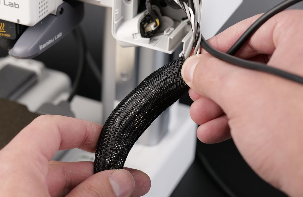
Step 2. Install the ferrite core attachment back to the cable in the original location.

¶ Install the USB-C cable to the cable box
Step 1. Put the USB-C cable in the cable box, and then close the buckle.
 |
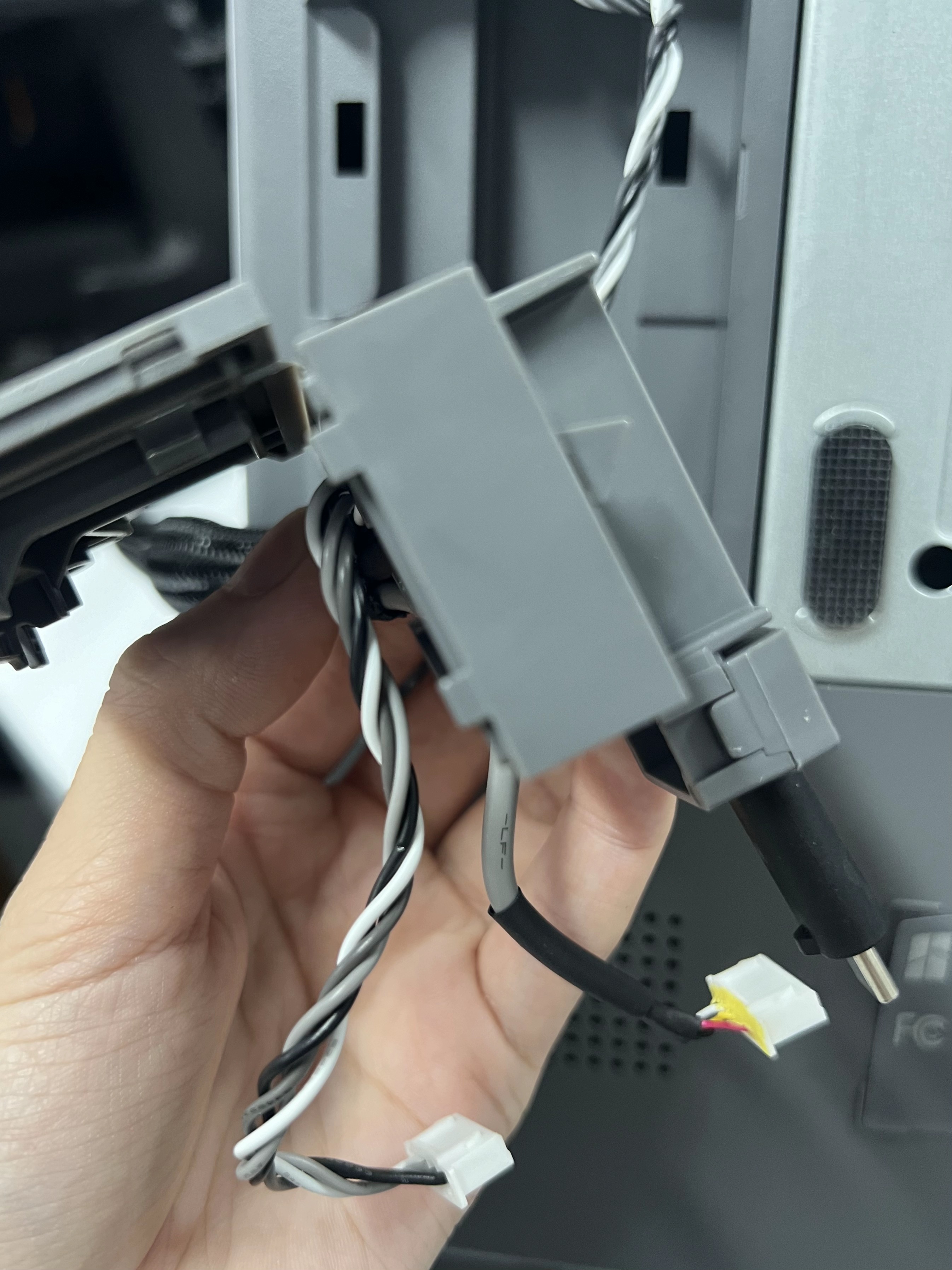 |
Step 2. Put the cables of X motor, Z motor, and camera to their respective slots, close the buckle and tighten the screw.
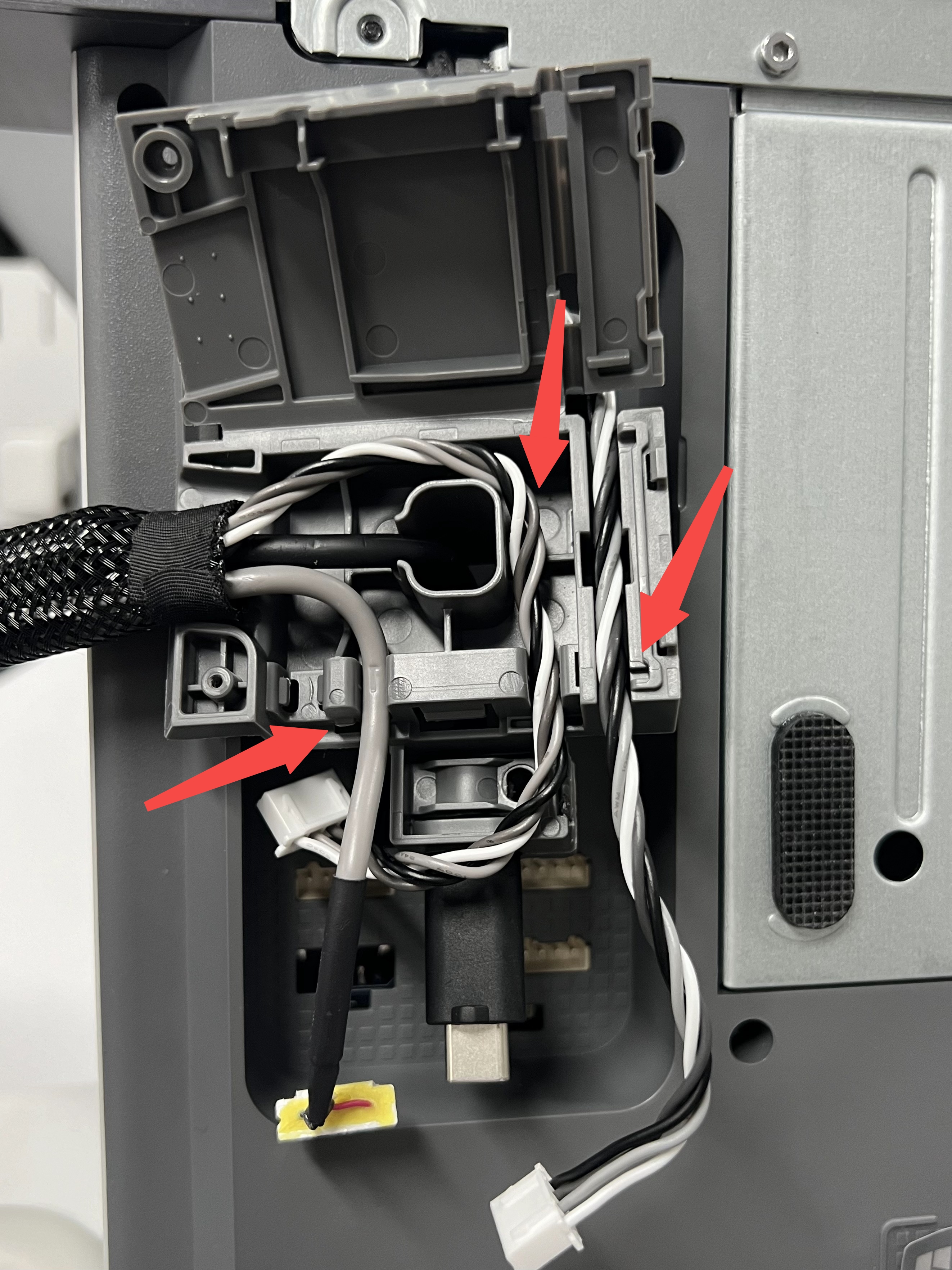 |
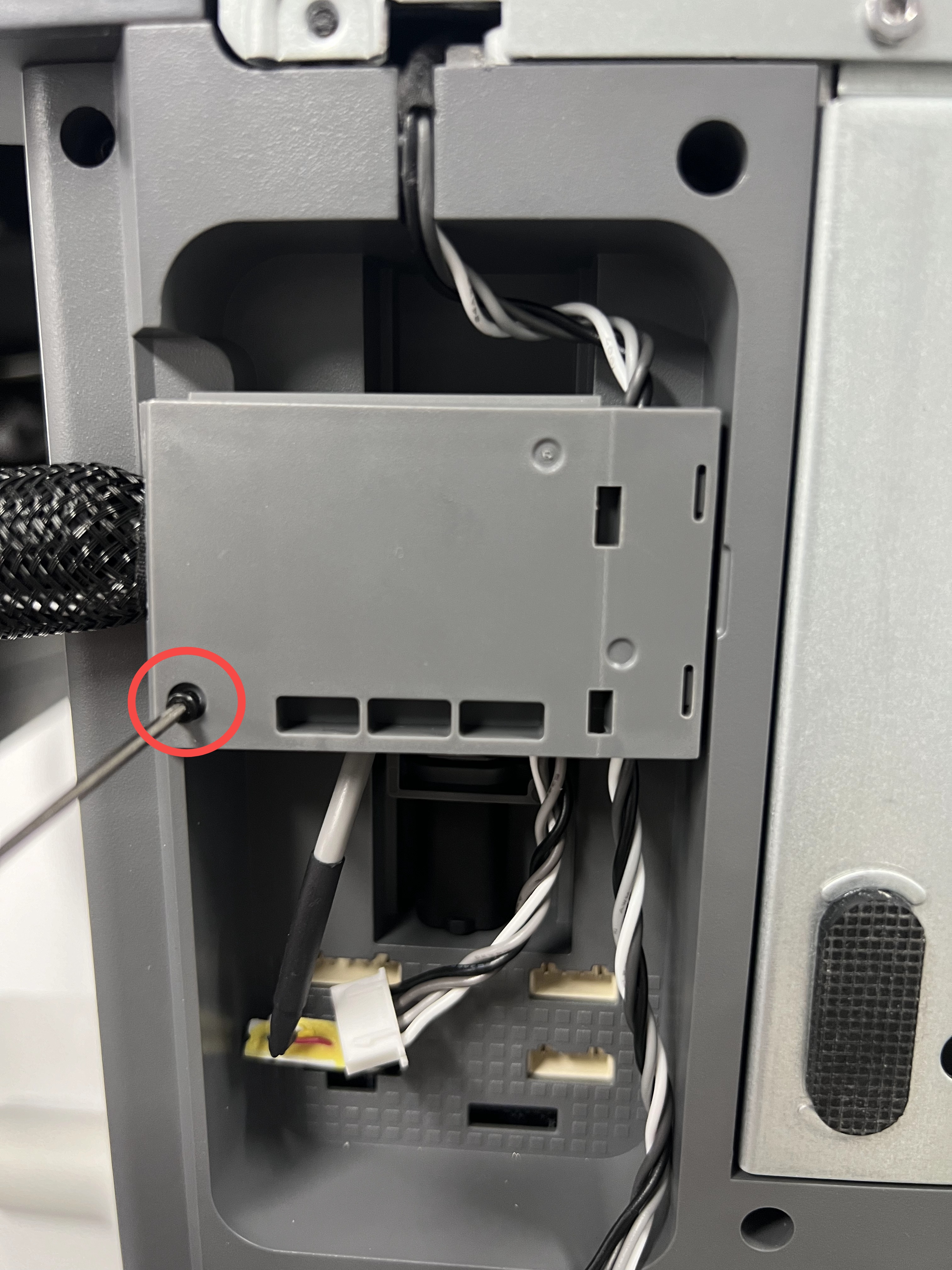 |
Please pay attention that there is a small bump which should be on the side of the cable as shown below.
Step 3. Carefully align the wire bracket then push it downwards while making sure the USB cable is fully pushed against the printer frame. Then, tighten the screw shown in the image to lock it in place. Avoid overtightening the screw as this is screwed into the plastic frame.
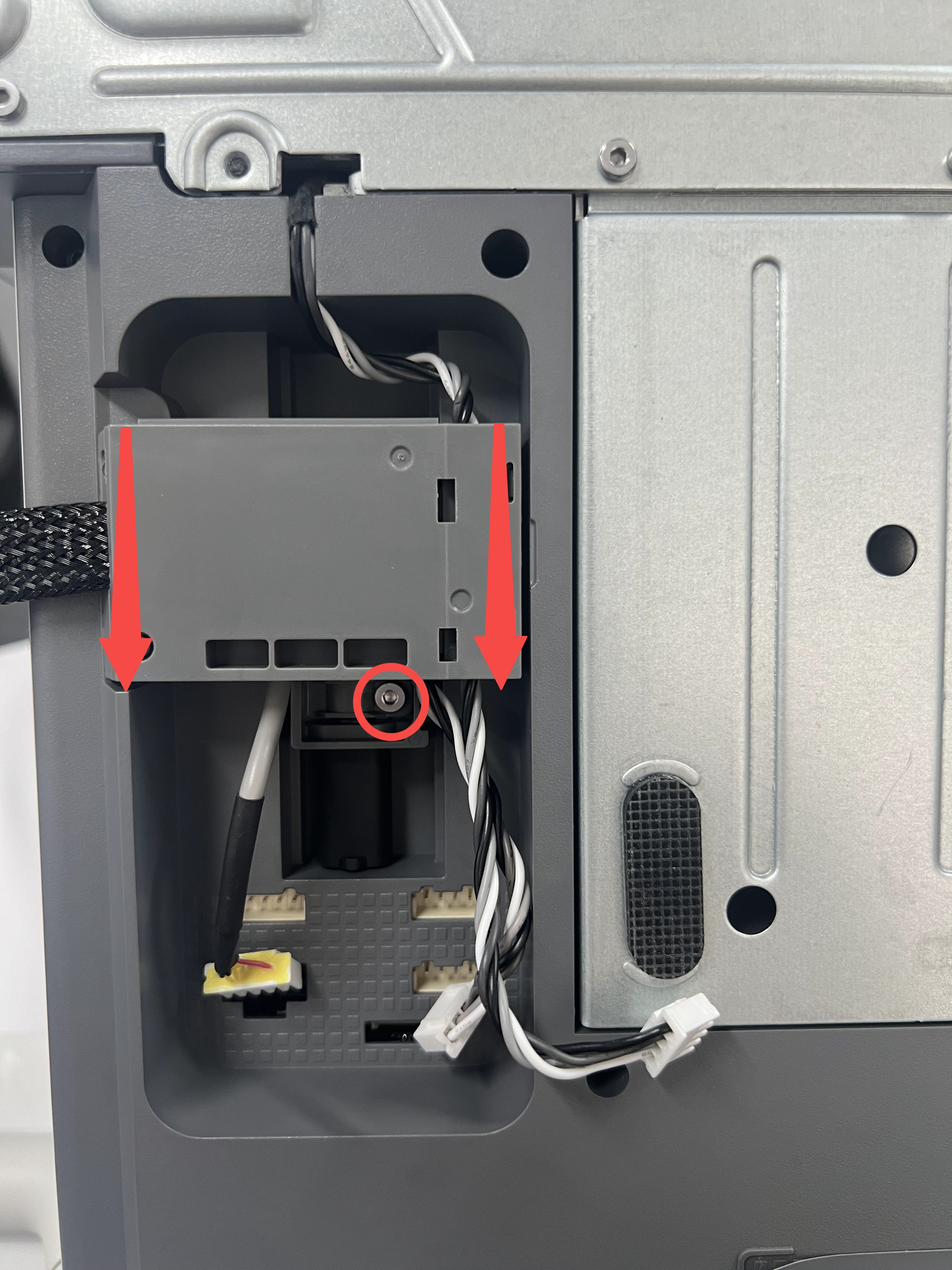
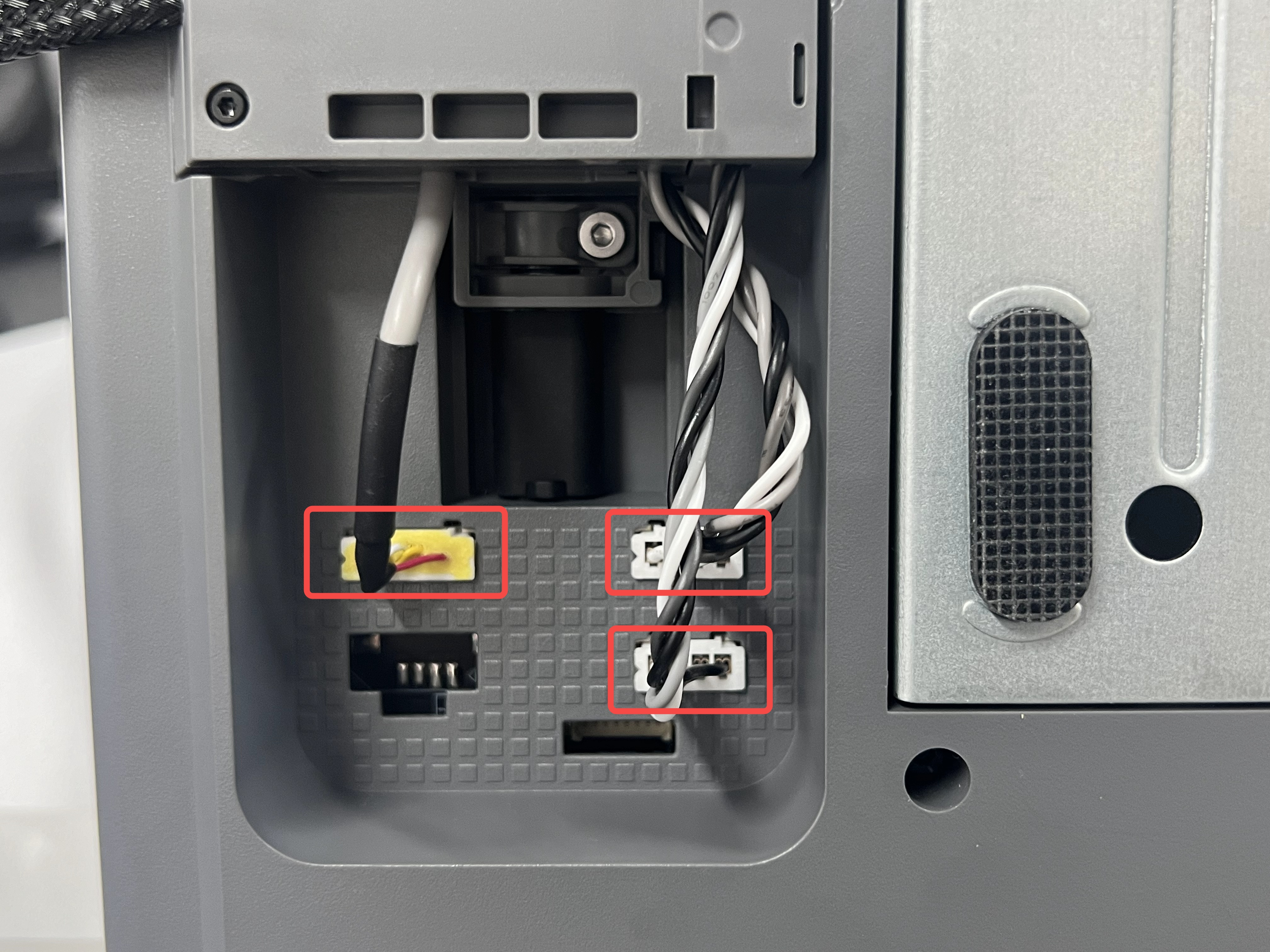
Step 4. Next, re-connect the Camera, X-axis motor and Z-axis motor cables to finish the installation.
Note: The shorter cable on the right is the X-axis motor cable, which connects to the upper right connector; The longer cable on the right is the Z-axis motor cable, which connects to the lower right connector.
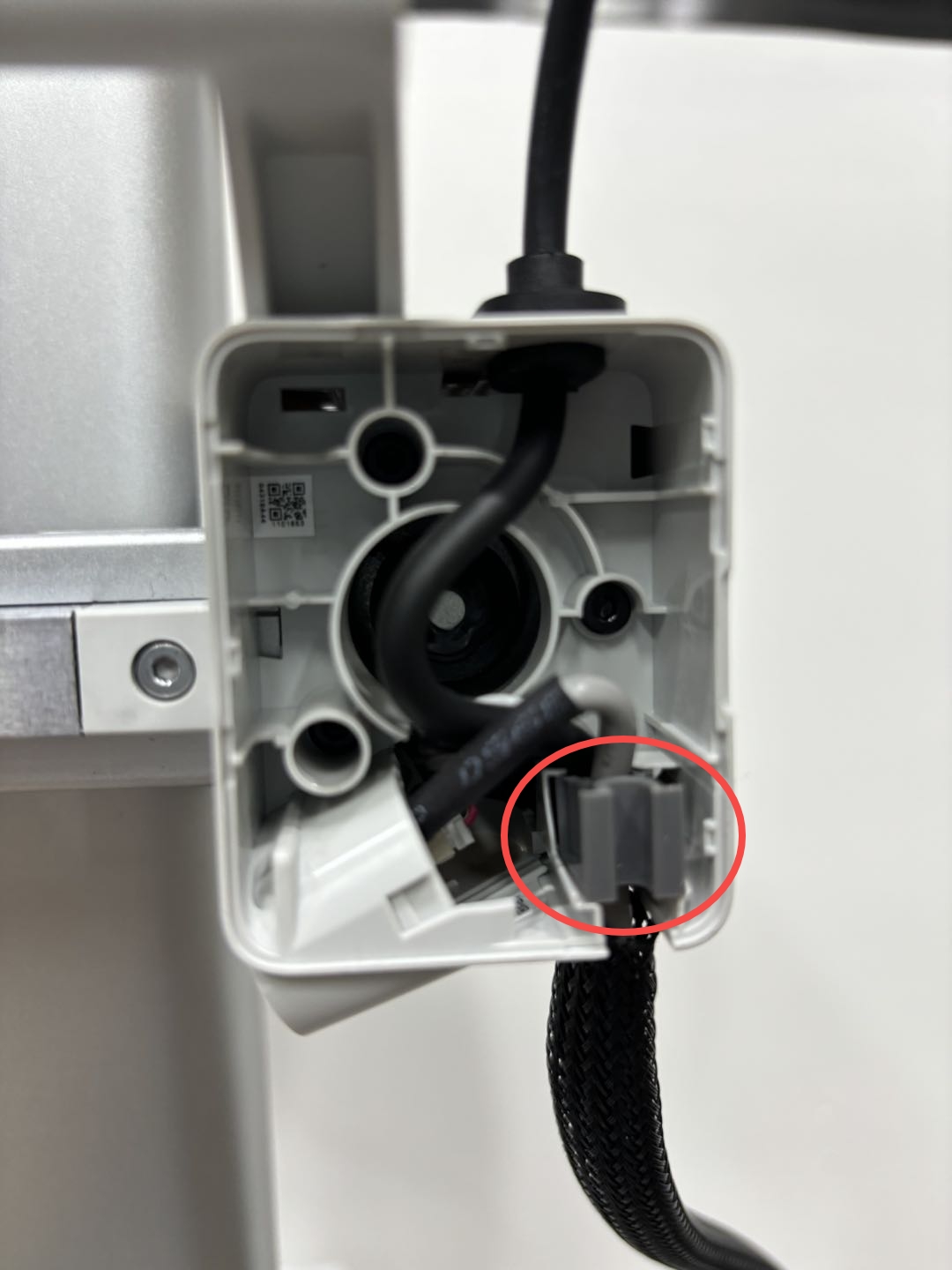
¶ Install the USB-C cable fixture and wire attachment
Step 1. Install the fixture to the X motor box.
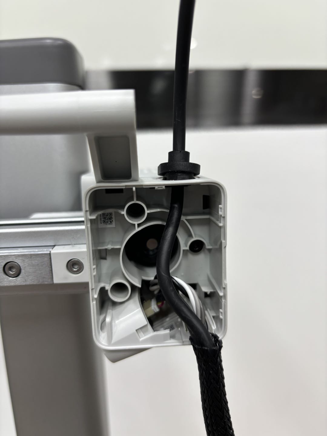
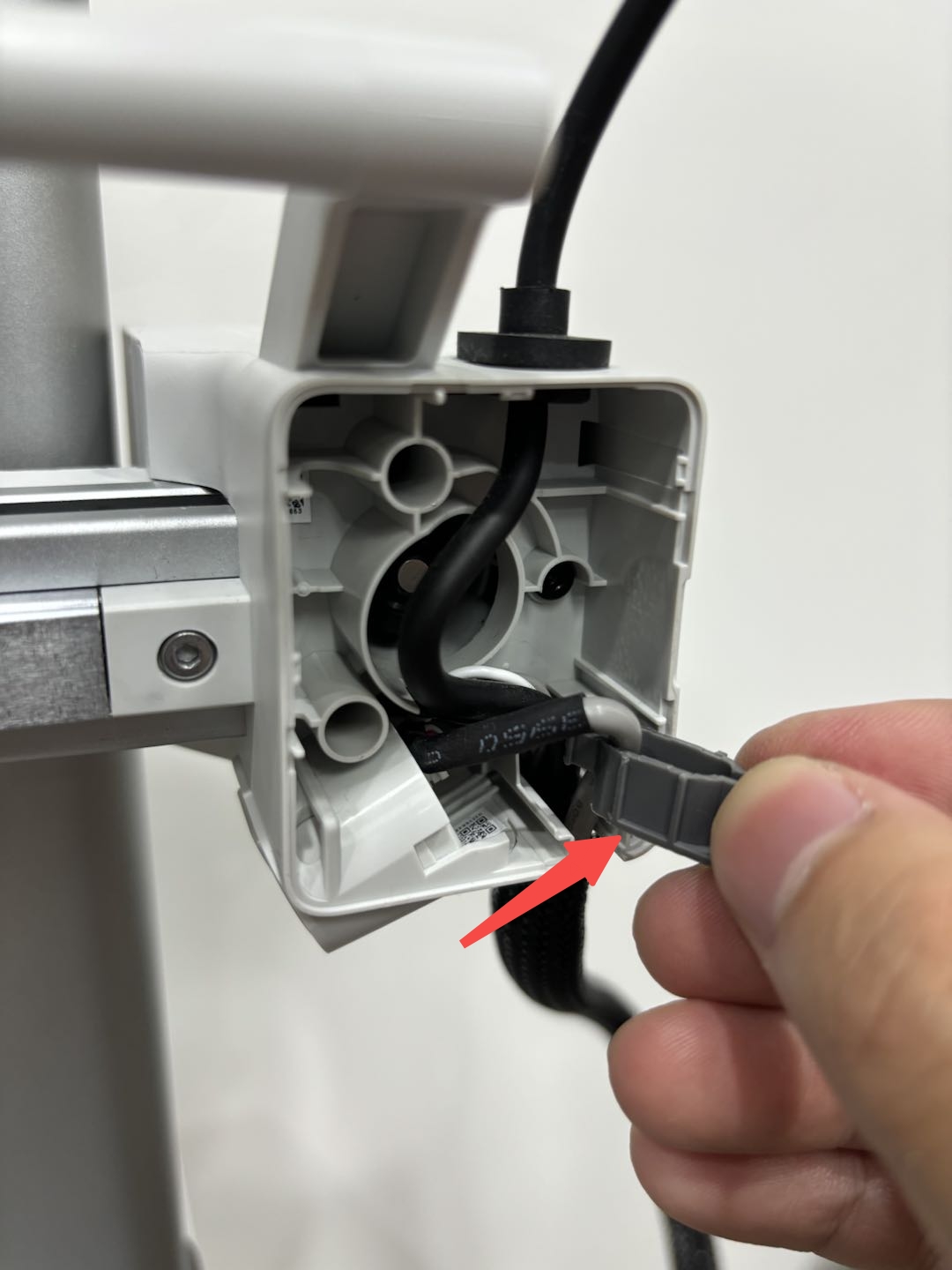
Step 2. Install the wire attachment as shown below.
 |
 |
 |
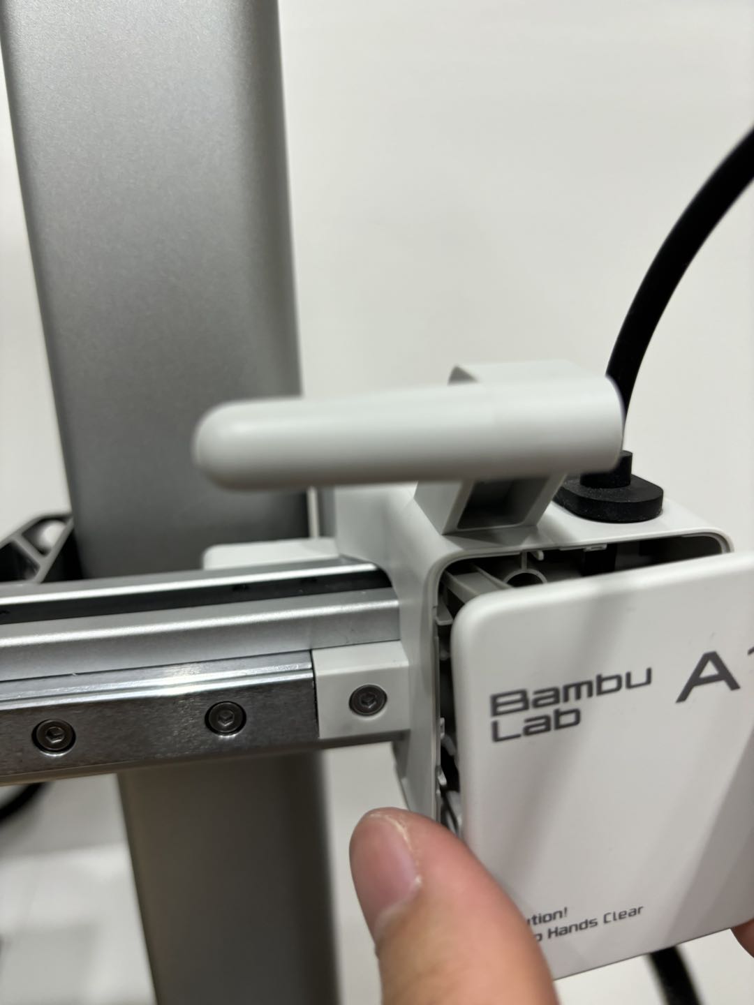
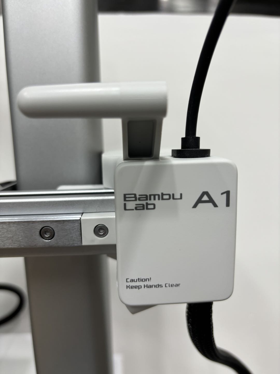
Step 3. Install the front cover back. You will hear a click sound that means success.
 |
 |
¶ Fix the USB-C cable to the toolhead
Insert the USB-C cable in the toolhead, then use the four screws to tighten it.
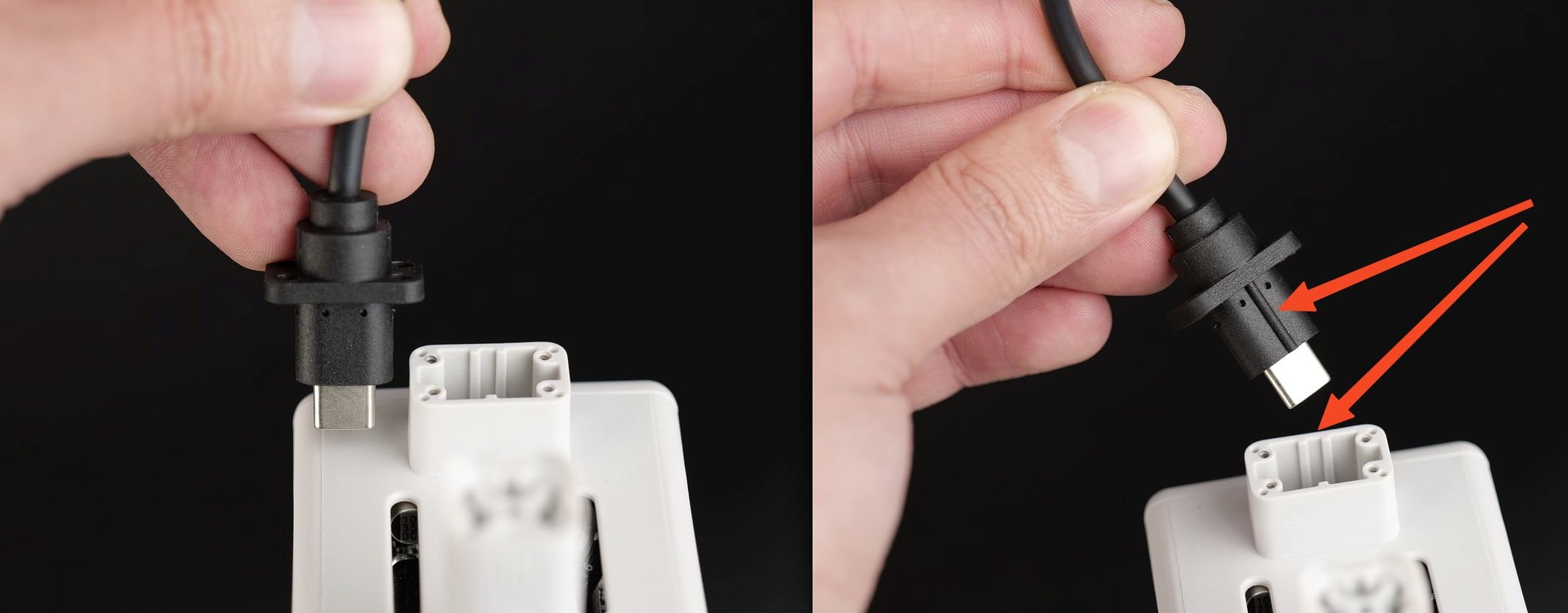
Important!
Please do not overtighten the screws to avoid damaging the threads. Also, please pay attention that USB-C cable should be aligned with the slot on the toolhead before inserting it.
¶ End Notes
We hope the detailed guide provided has been helpful and informative.
To ensure a safe and effective execution, if you have any concerns or questions about the process described in this article, we recommend submitting a technical ticket regarding your issue. Please include a picture or video illustrating the problem, as well as any additional information related to your inquiry.
