¶ Applicable models of printers
A1 mini
¶ X-belt for A1 mini
The X-belt is installed on the X-axis. It connects the toolhead with the X motor and drives the toolhead to move along the X-axis.
¶ When to use?
- It is worn.
- It is broken.
¶ Safety Warning
IMPORTANT!
It's crucial to power off the printer before conducting any maintenance work, including work on the printer's electronics and tool head wires. Performing tasks with the printer on can result in a short circuit, leading to electronic damage and safety hazards.
During maintenance or troubleshooting, you may need to disassemble parts, including the hotend. This exposes wires and electrical components that could short circuit if they contact each other, other metal, or electronic components while the printer is still on. This can result in damage to the printer's electronics and additional issues.
Therefore, it's crucial to turn off the printer and disconnect it from the power source before conducting any maintenance. This prevents short circuits or damage to the printer's electronics, ensuring safe and effective maintenance. For any concerns or questions about following this guide, we recommend submitting a technical ticket regarding your issue and we will do our best to respond promptly and provide the assistance you need.
¶ Tools and materials needed
- New X-belt (Purchase link: X Belt - A1 mini)
- H2.0 hex wrench
- tweezer
- 20 minutes
¶ Remove the X-belt
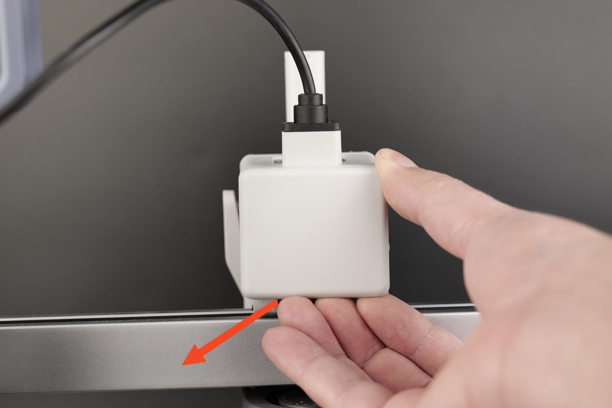
¶ Remove the rear cover of the toolhead
Please carefully pull the bottom of the rear cover by hand, as shown below:
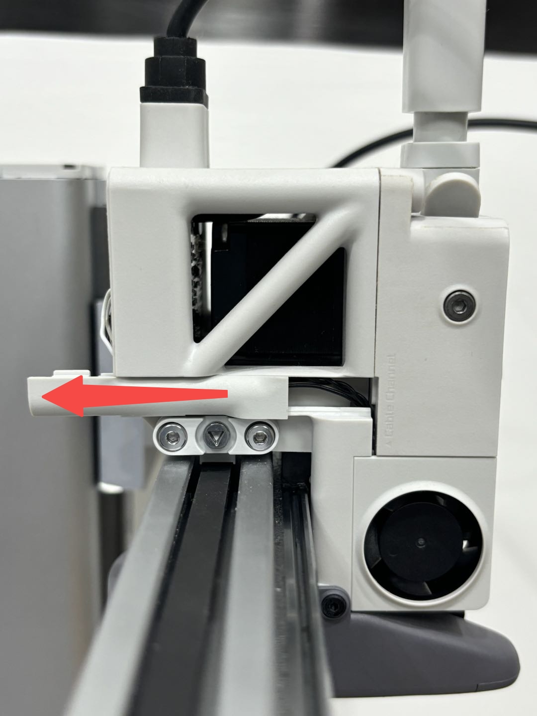
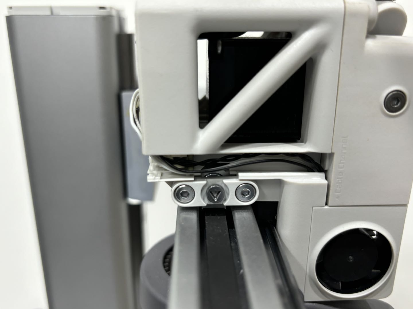
¶ Remove the left cable cover
Gently push the cable cover to the back of the toolhead, and then remove the cable cover on the left side. Please refer to the figure below for specific operations:
 |
 |
|---|
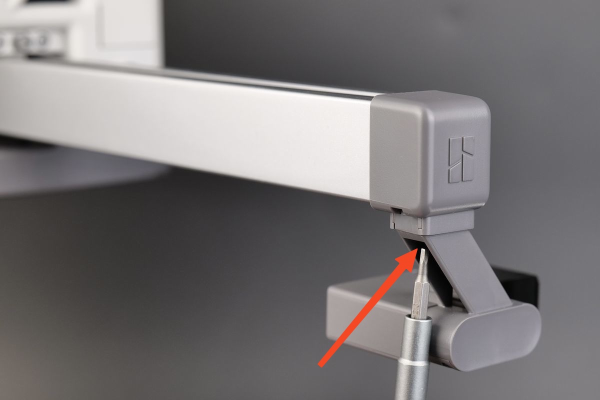
¶ Remove the purge wiper and X-axis cover
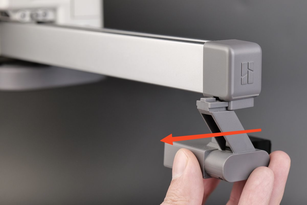
Step 1: Loosen the screws located under the purge wiper, and then slide the purge wiper out of the bracket in the direction shown in the picture:
 |
 |
|---|
Step 2: Remove the X-axis Cover
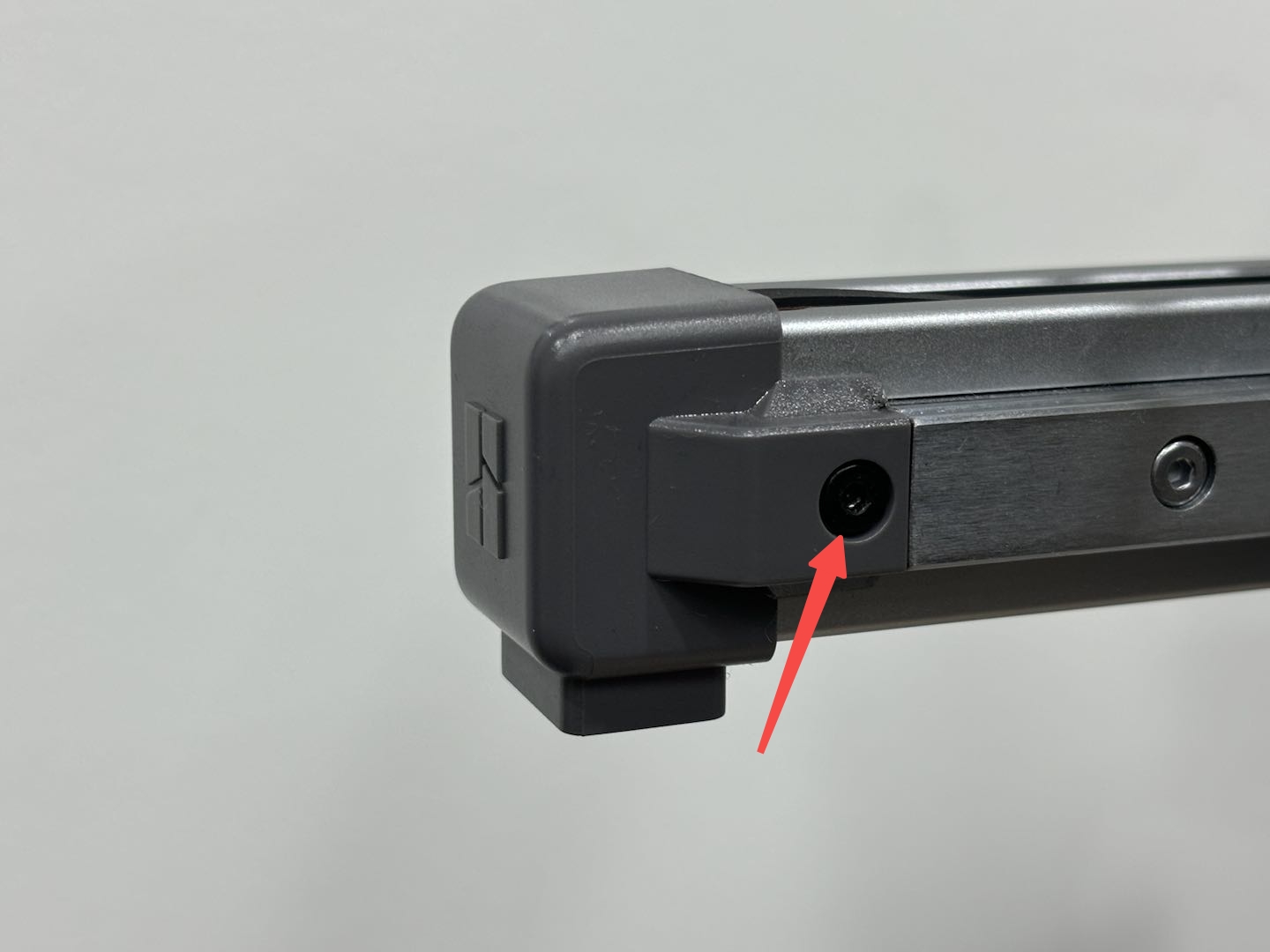
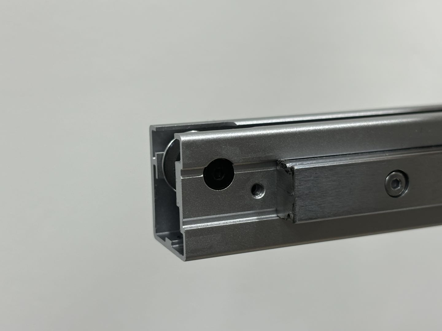
Use H2.0 hex wrench to remove one screw, and remove the X-axis cover.
Note: The cover screw is shorter than the purge wiper screw. Please distinguish the two screws to avoid errors during subsequent installation.
 |
 |
|---|
¶ Remove the X motor cover
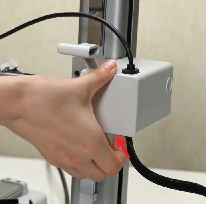
Apply force from below the front cover of motor to remove it.
¶ Remove the X-belt
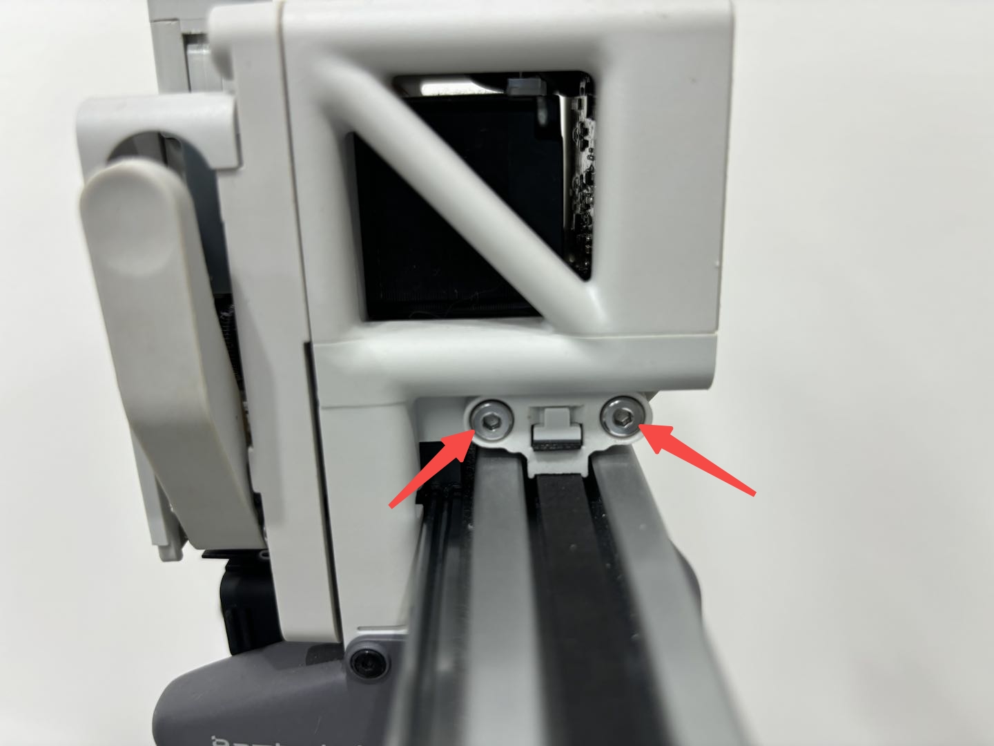
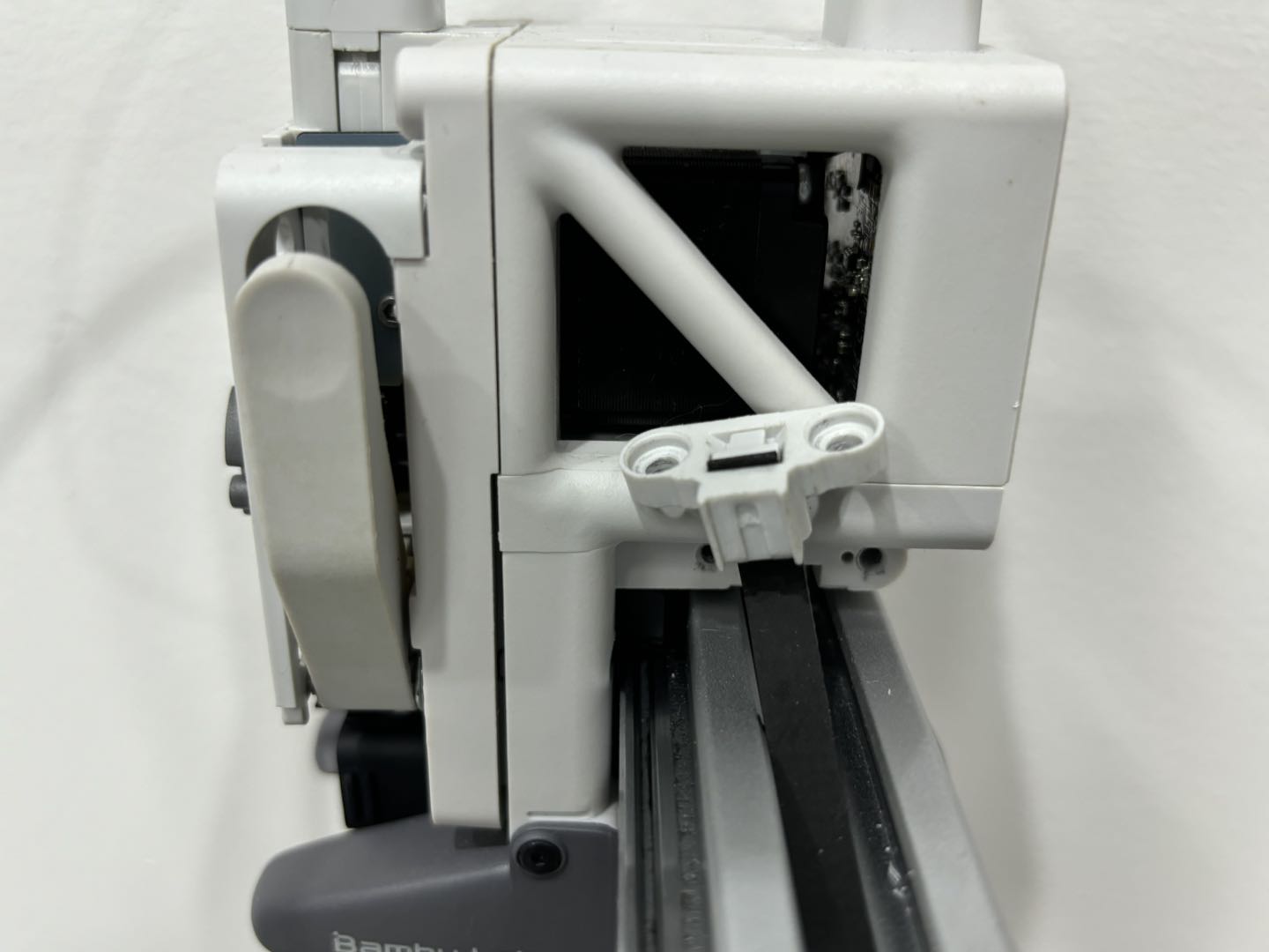
Step 1: Loosen two screws and pull the clamp out of the toolhead;
 |
 |
|---|
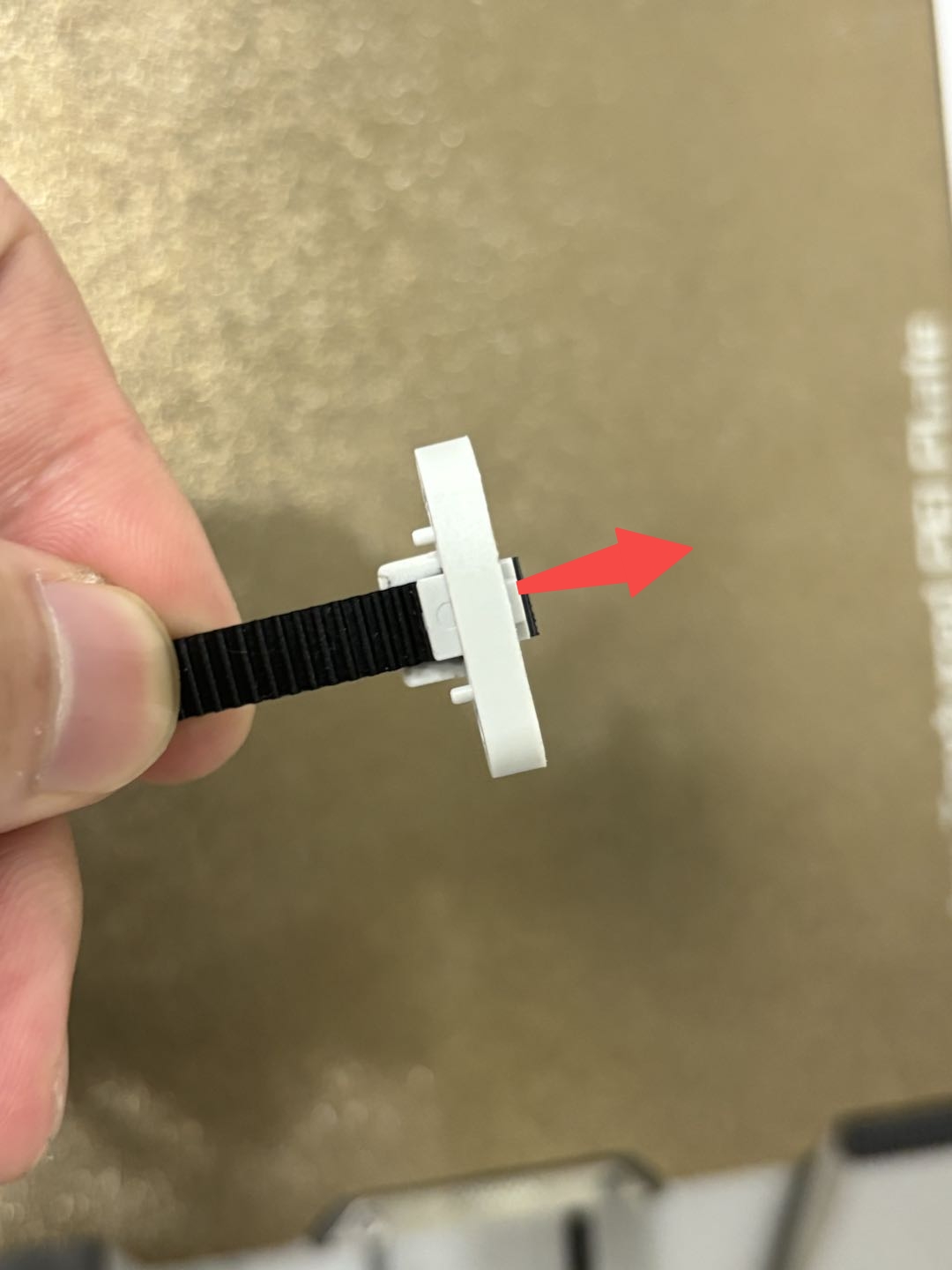
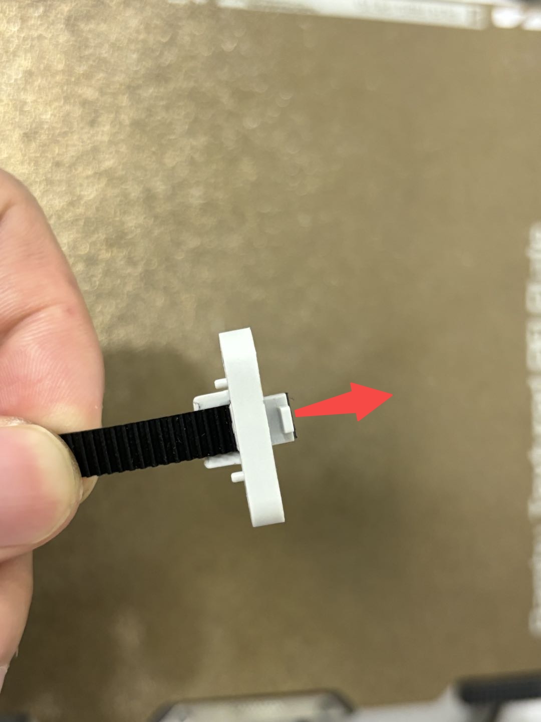
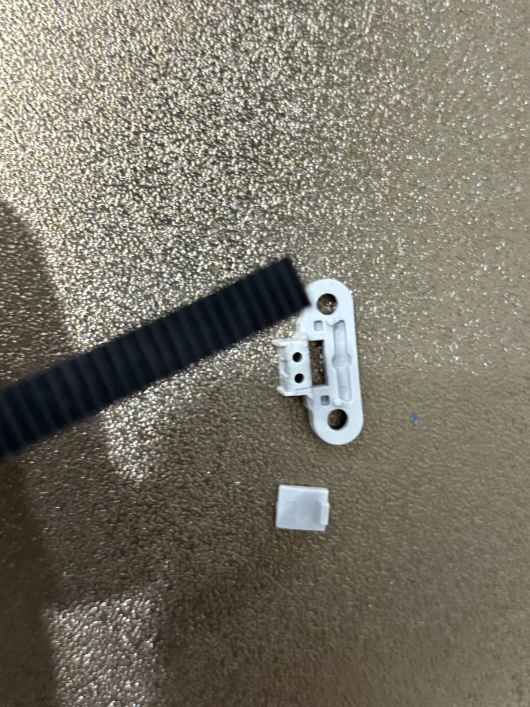
Step 2: After loosening the belt, hold the belt clamp and remove the belt from the clamp.
 |
 |
 |
|---|
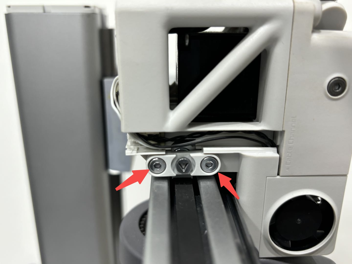
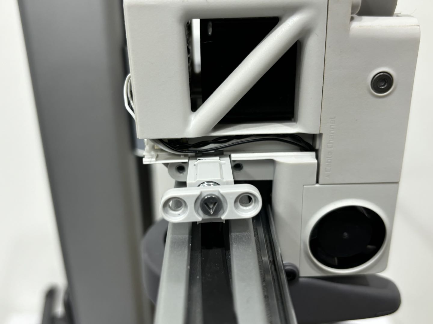
Step 3: Loosen the screws behind the toolhead, and remove the screw and iron piece;
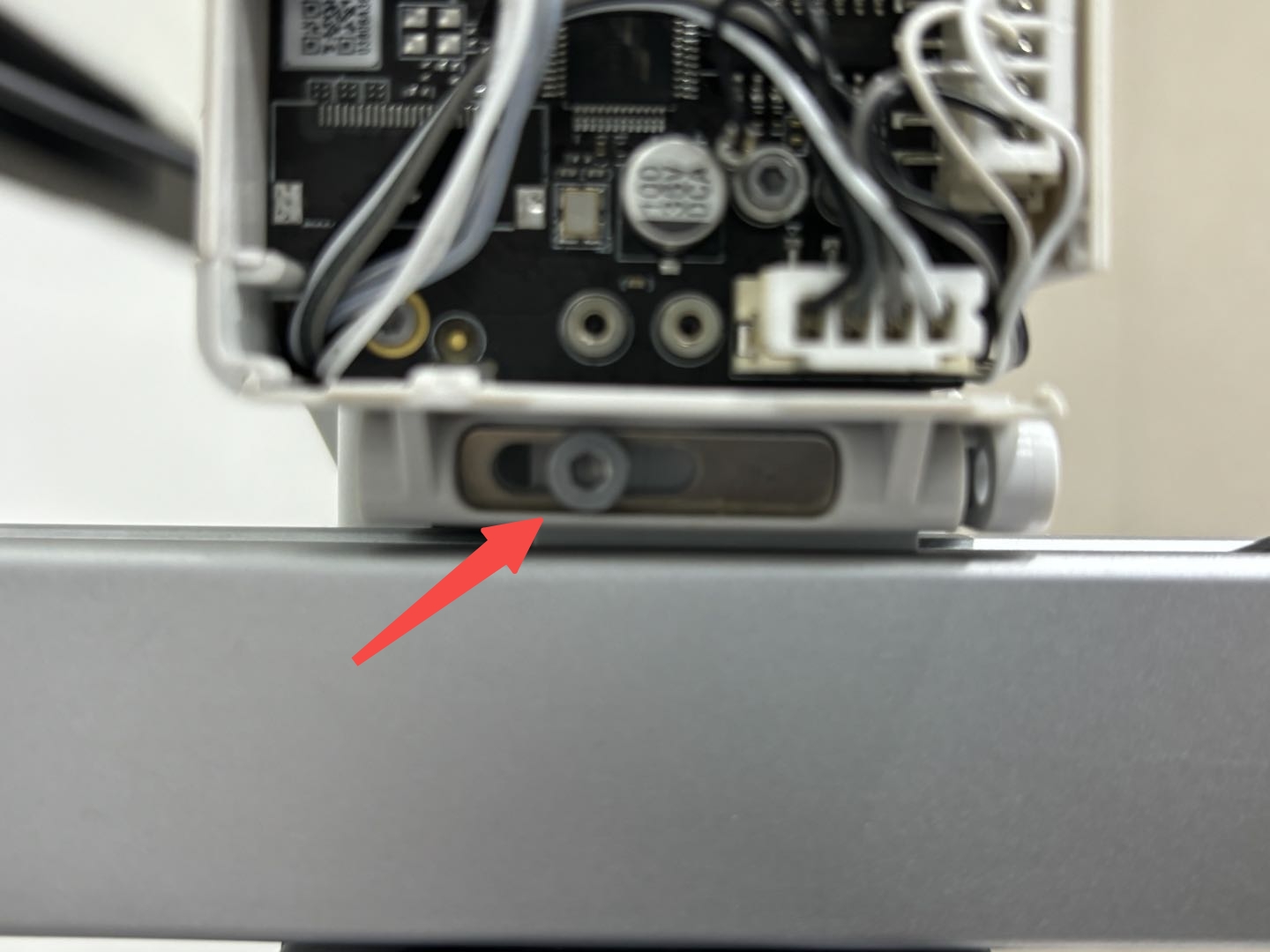
Loosen two screws, and remove the left clamp.
 |
 |
|---|
Step 4: Hold the left belt clamp, and pull out the X-belt.
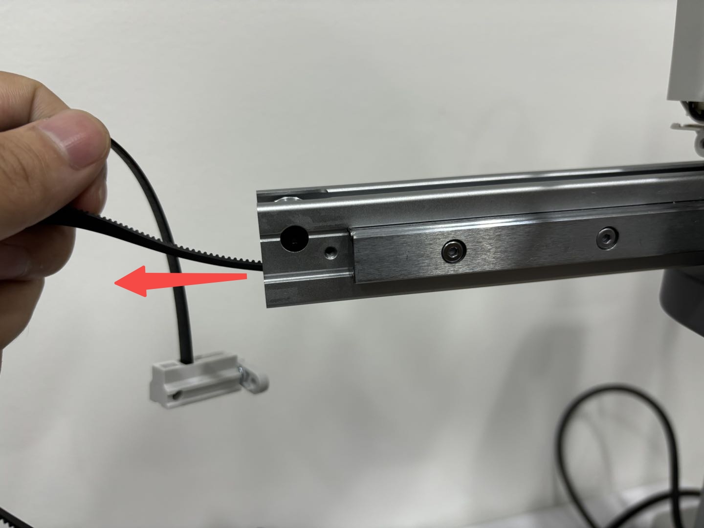
¶ Install the X-belt
¶ Thread the X-belt onto the X-axis
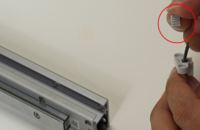
Step 1: The left and right clamps are pre-installed on the X-belt, and the hole between the motor cover and the X-axis is small. Thus, after getting the new belt, please seperate the right clamp from the X-belt in advance, and then reinstall the right clamp after threading the X-belt. The method of removing the belt from the right clamp is as follows:
 |
 |
 |
|---|
Step 2: Check the direction of the belt, with the tooth facing upward, and thread the belt through the X-axis from the lower side of the idler;
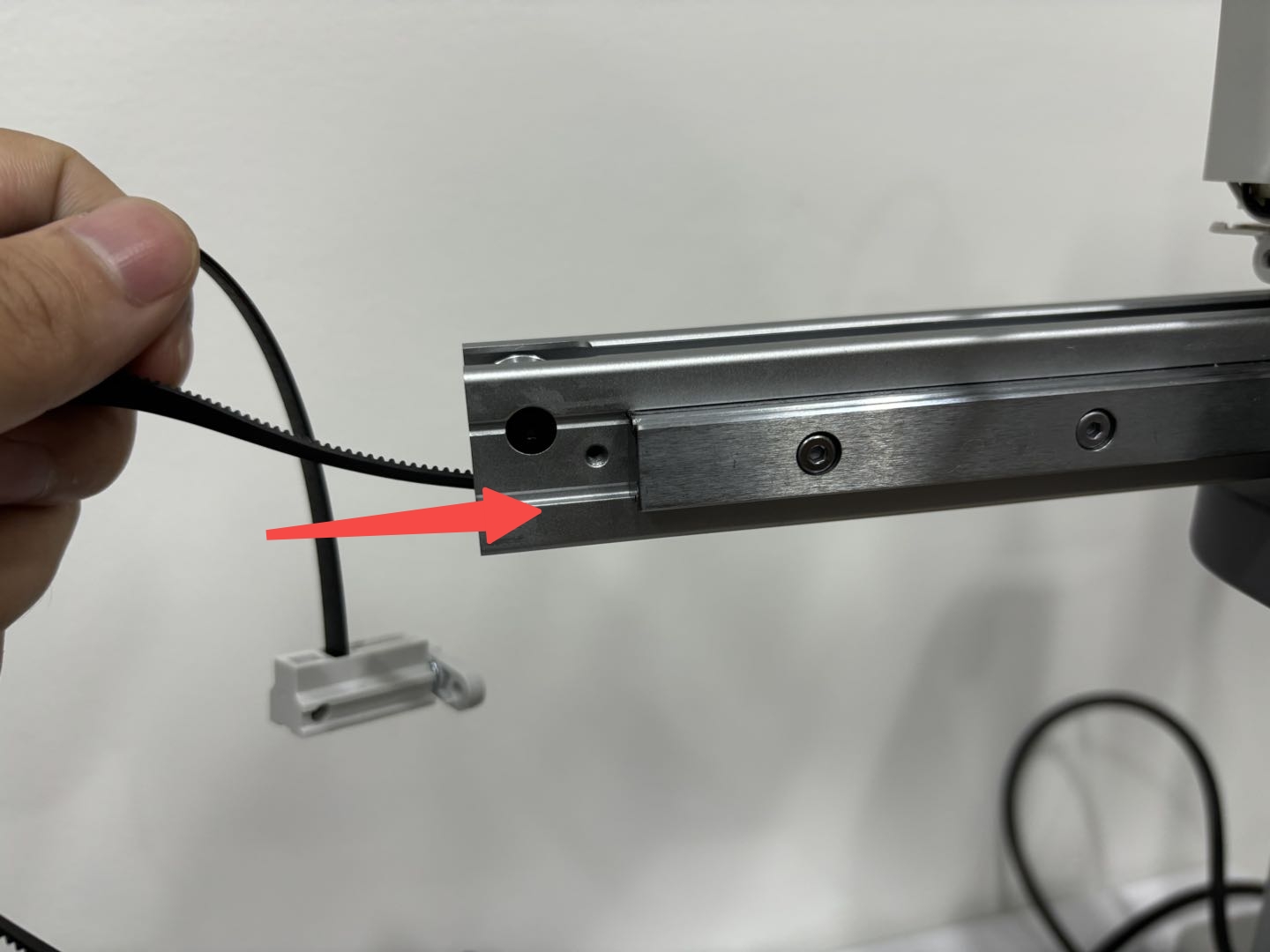
Then clip the belt with tweezer, pass the X-belt around the motor drive wheel, and thread X-belt out through the small hole between the X-axis and the motor cover.
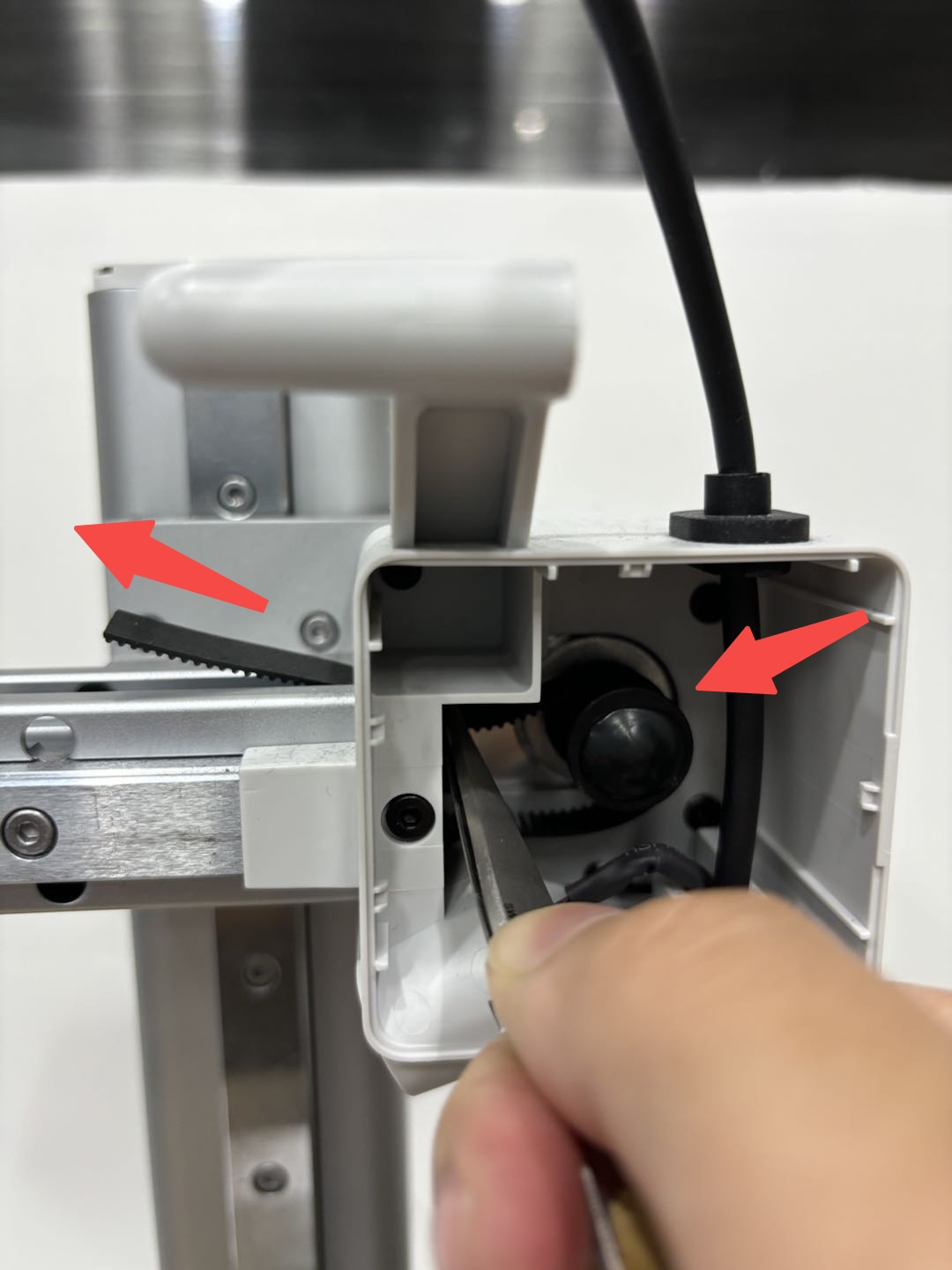
Step 3: Insert the left clamp into the toolhead and tighten the screws. Then re-install the iron piece to the back of the toolhead and tighten the screw.
 |
 |
|---|
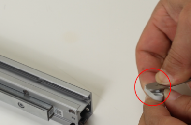
Step 4: Thread the belt through the right clamp, align the belt with the belt tensioner, and press them together into the clamp;
.jpg) |
 |
 |
|---|
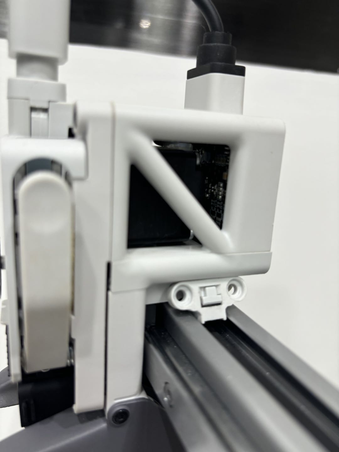
Then install the right clamp into the toolhead, and tighten the screws.
 |
 |
|---|
¶ Reinstall the motor cover
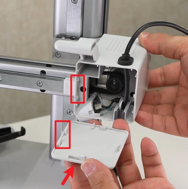
Check the installation direction, and close the front cover of X motor.
¶ Reinstall the purge wiper and X-axis cover
Step 1: Insert the X-axis cover into X-axis, and tighten the screw.
Note: The cover screw is shorter than the purge wiper screw. If used incorrectly, the purge wiper screw will hit the X-axis idler pulley, causing abnormal X-axis resistance and continuous step loss when homing.

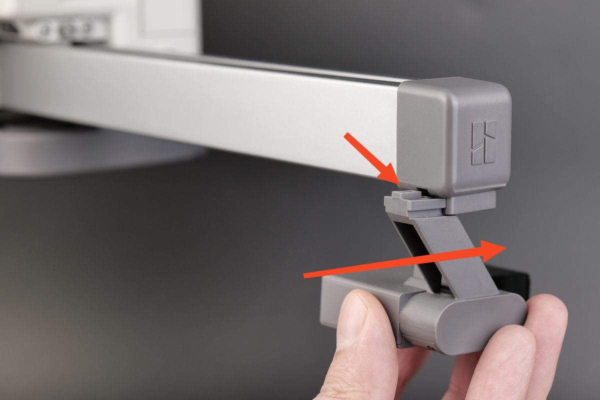
Step 2: Align the slot of the purge wiper with the bracket, slide it in until the surface is flush, then reinsert the screw into the original position and tighten it again.
 |
 |
|---|
¶ Tension the X-belt
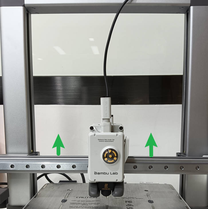
Step 1: Turn on the power and operate the printer. Move the X-axis to the position close to the middle of the Z-axis to avoid scratching the hotbed when moving the toolhead, and turn off the printer;
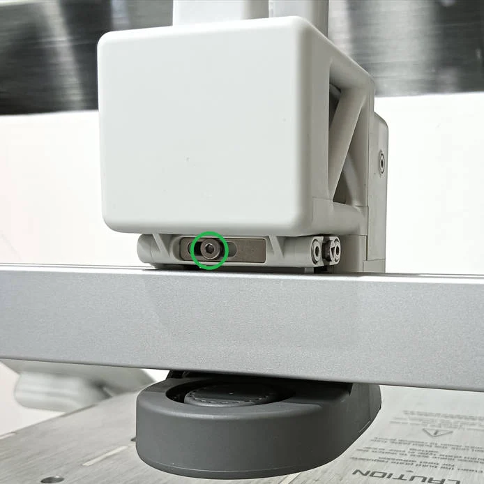
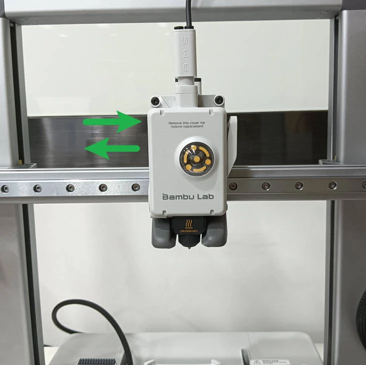
Step 2: Use the H2.0 hex wrench to loosen the tension screw one turn (do not loosen completely), move the toolhead back and forth along the X-axis three times by hand, and then re-tighten the tension screw.
 |
 |
|---|
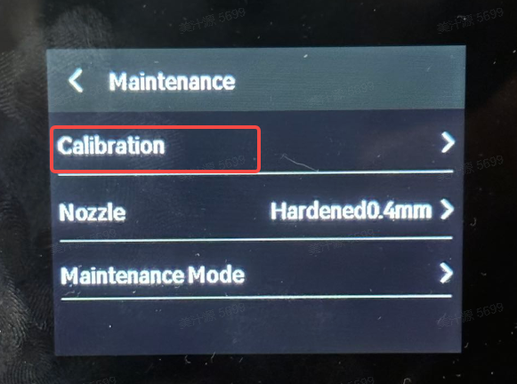
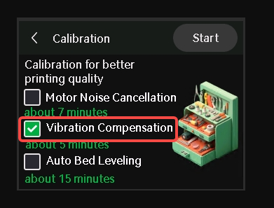
Step 3: Start the printer, select Vibration Compensation in the calibration menu, and complete the calibration process.
 |
 |
|---|
¶ End Notes
We hope the detailed guide provided has been helpful and informative.
To ensure a safe and effective execution, if you have any concerns or questions about the process described in this article, we recommend submitting a technical ticket regarding your issue. Please include a picture or video illustrating the problem, as well as any additional information related to your inquiry.